Composite Structure Having an Ice Protection Device, and Production Method

a technology of ice protection device and composite structure, which is applied in the direction of electric heating circuit, heating element materials, electric vehicles, etc., can solve the problems of stalling and loss of lift force, affecting the air flow over the surface concerned, and affecting the airflow over the surface concerned. , to achieve the effect of easy embedding in the composite structur

Active Publication Date: 2014-06-05
EADS DEUT GMBH
View PDF4 Cites 39 Cited by
  • Summary
  • Abstract
  • Description
  • Claims
  • Application Information

AI Technical Summary

Benefits of technology

[0016]Exemplary embodiments of the present invention are directed to an ice protection system for an aircraft that avoids at least some of the aforementioned drawbacks.
[0025]Even more highly preferred is that the heating element is designed as a textile surface structure that can be easily embedded in the composite structure. Preferably the textile surface structure comprises a carbon felt. Such a surface structure can be infiltrated by a matrix material or a cover layer material during application and, as a result, can be almost integrated in the composite structure.

Problems solved by technology

If a layer of ice grows, it has an adverse effect on the air flow over the surface concerned.
If the layer is large enough, it can cause carrying or lifting problems or handling problems for the aircraft.
In the worst case scenario the net result of such problems can be a stall and loss of lift force.
Pneumatic de-icing profiles, which remove ice by means of surface movements induced by air pressure, can only be used for a low speed aircraft.
However, the engine bleed temperature is usually too high for aircraft components made of composite materials, such as carbon fiber-reinforced plastic (CFRP) structures.
Diverting the hot air results in a degradation of the efficiency of the engine.
The heating elements that are embedded in rubber layers have drawbacks in terms of low electrical efficiency, in terms of a high weight and with regard to installing the heating elements.
Such heating elements cannot be installed on just any surface structure.
That is, the design freedom with respect to surfaces that are to be protected is extremely limited.
The heating surfaces have a short service life.
Such ice protection systems require high production and maintenance costs and do not lend themselves to small aircraft components, such as dynamic pressure sensors or the like.
The weeping wing systems constantly consume fluids during the flight, need nozzles on the leading edge of the wing, and pollute the environment.
They are maintenance intensive and necessitate a high weight, since the fluid must be refilled and carried along.
The EMEDS systems have disadvantages in terms of their high weight and with respect to the need for special adaptation of the composite structures to the actuators and their knocking movements.
Moreover, such systems cannot prevent the formation of ice, but rather can only remove the ice that has accumulated.
The removed ice can damage or destroy the engine rotors during the flight.

Method used


Image

  • Composite Structure Having an Ice Protection Device, and Production Method
  • Composite Structure Having an Ice Protection Device, and Production Method
  • Composite Structure Having an Ice Protection Device, and Production Method

Examples


first embodiment

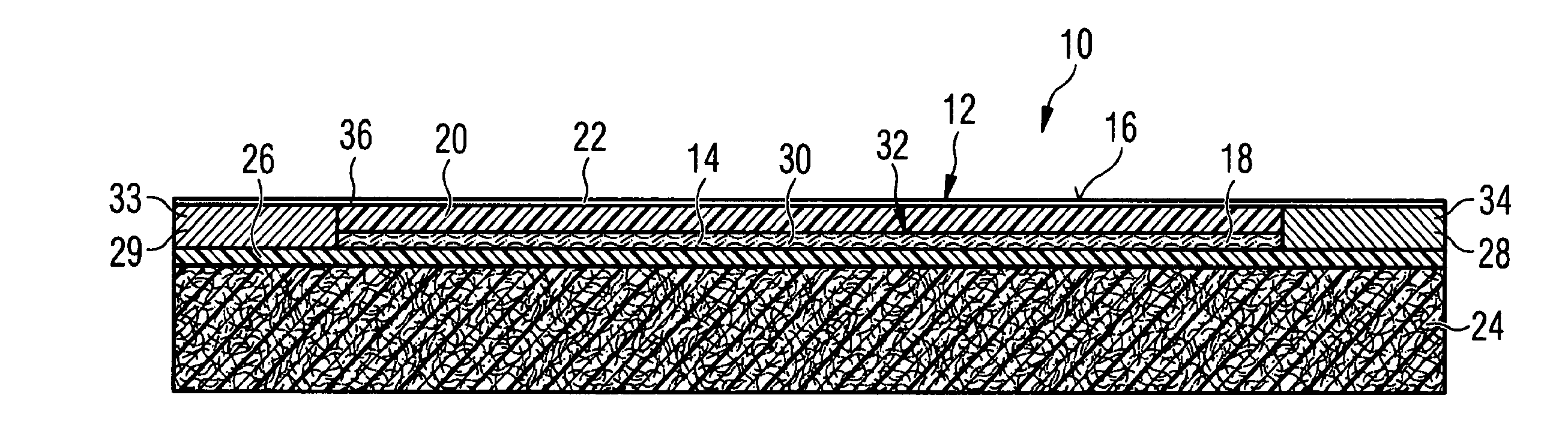
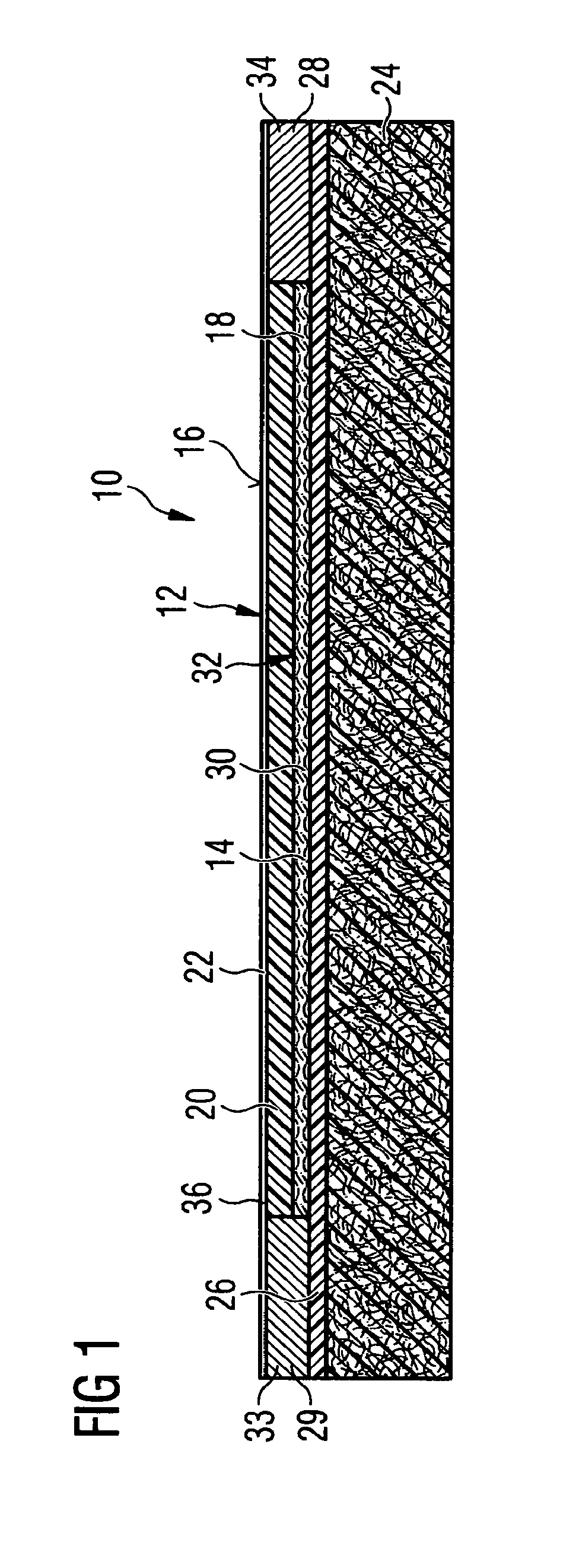
[0057]The electric heating element 14 is a two-dimensional sheet, in order to form a heating layer 18 that is arranged below the outer cover layer 20 of the composite structure. The outer cover layer 20 is formed, in particular, by means of a finish top coat 22. The construction of the composite structure 10 is explained in detail below with reference to the drawing in FIG. 1.

[0058]The composite structure 10, shown in FIG. 1, has a composite material substrate 24 made of a fiber reinforced composite material.

[0059]In particular, the composite material substrate 24 is formed from a carbon fiber reinforced plastic material. The plastic material is, in particular, epoxy resin. Correspondingly the composite material substrate 24 is formed, in particular, from a CFRP material.

[0060]An insulating layer 26, made of an electrically insulating material, is applied on this composite material substrate 24. The insulating layer 26 is formed, in particular, from epoxy resin.

[0061]Between the com...

second embodiment

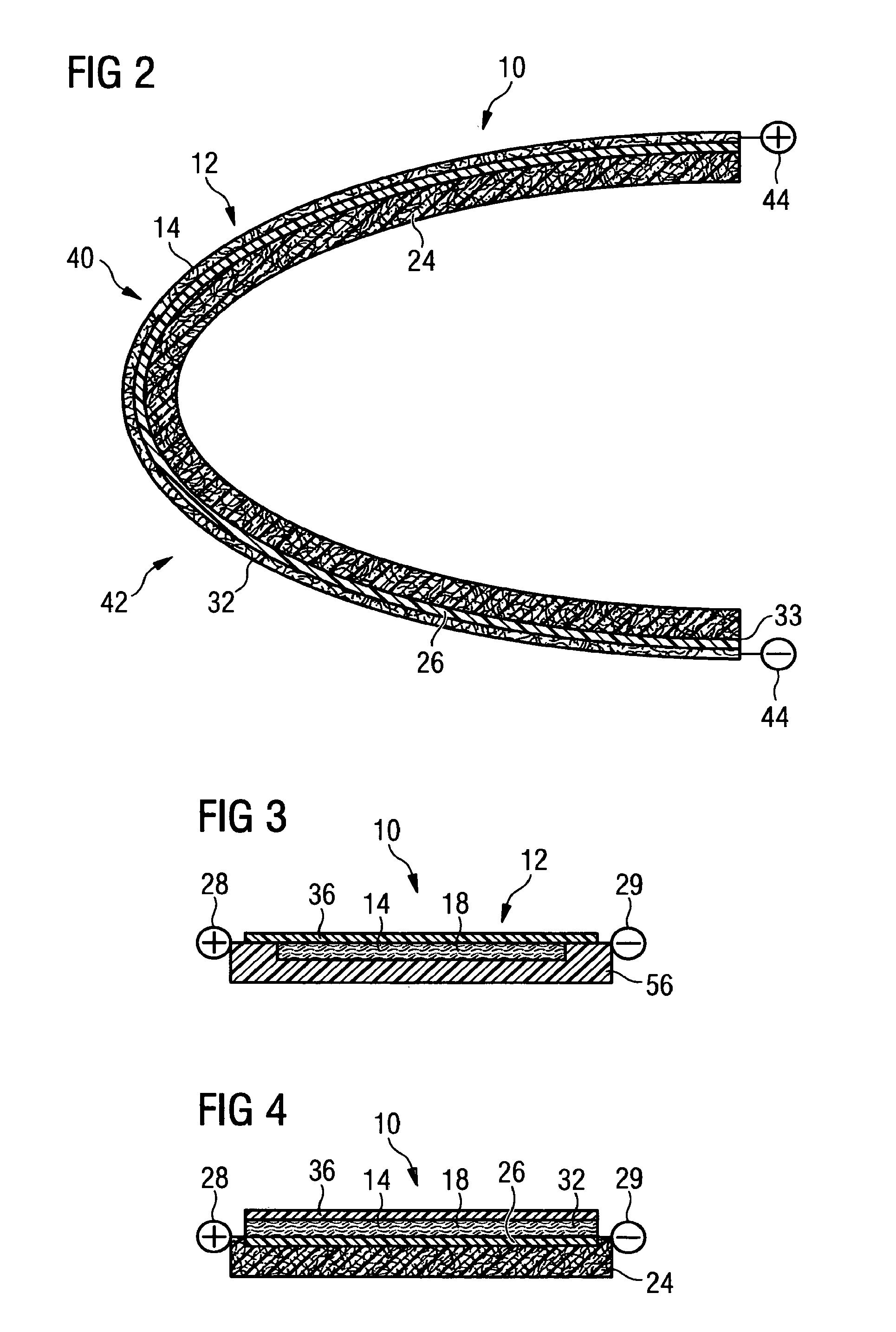
[0100]In the second embodiment shown in FIG. 3, a carbon felt 32 is embedded as the heating element 14 in a thermoplastic resin, for example PPS or PAA, and covered with the PEEK coating 36 as the finish top coat 22. The carbon felt 32 is, for example, a felt that is available under the tradename SIGRATEX®. The thermoplastic resins for embedding this felt 32 are available on the market, for example, under the tradename FORTRON® or IXEF®. The felt 32 is generally embedded in a synthetic plastic material 56.

[0101]In the third embodiment, shown in FIG. 4, a silicone rubber, which vulcanizes into a silicone gel, is provided as the material for the insulating layer 26. One example of said silicone rubber is the material that is available under the brand name SIL-Gel®. Hence, the composite structure 10, according to the third embodiment shown in FIG. 4, is constructed from the bottom to the top as follows: the composite material substrate 24; the insulating layer 26 using the SIL-Gel, the...

fourth embodiment

[0102]In the composite structure 10 shown in FIG. 5, a latent heat storage device 46 is also provided additionally below the heating layer 18 with the electric heating element 14. The latent heat storage device 46 is designed as a latent heat storage panel 48 that can store the latent heat by using an embedded material that has a phase transition at the temperature of interest.

[0103]Such a latent heat storage panel 48 is formed, for example, from a composite material made of a material, which exhibits a phase transition occurring at the temperatures under discussion herein, and carbon. Such a latent heat storage panel 48 is available on the market, for example, under the brand name ECOPHIT®.


PUM

PropertyMeasurementUnit
thicknessaaaaaaaaaa
thicknessaaaaaaaaaa
widthaaaaaaaaaa

Abstract

An ice protection system for de-icing an aircraft and / or for keeping the aircraft free of ice includes a composite structure for an aircraft component and a structural element of an aircraft with an ice protection system that is integrated in the composite structure. The ice protection system includes a flat surface-like electric heating element that is embedded in the composite structure below an outer layer of an outer surface of the aircraft component.

Description

BACKGROUND AND SUMMARY OF THE INVENTION[0001]Exemplary embodiments of the invention relate to a composite structure for an aircraft component, in order to form a structural element of an aircraft, as well as a method for producing the composite structure.[0002]The invention deals, in particular, with the problem of ice forming on an aircraft and, hence, also relates to the field of ice protection systems that include both systems for preventing the formation of ice on an aircraft as well as systems for de-icing an aircraft.[0003]Ice forms on the leading edges of wings, tails and horizontal stabilizers, when an aircraft, such as an airplane or a helicopter, flies through a cloud that contains supercooled water droplets. The ice forms, as the supercooled water droplets of clouds touch the aircraft. This contact introduces energy into the droplet and causes them to change from the liquid state to the solid state and, thus, to become ice. If a layer of ice grows, it has an adverse effec...

Claims


Application Information

Patent Timeline
Patent Type & Authority Applications(United States)
IPC IPC(8): B64D15/12
CPCB64D15/12H05B3/145H05B3/18H05B3/26H05B3/28H05B2214/02H05B2214/04Y10T29/49083
Inventor STEINWANDEL, JUERGENENGLHART, MARTINJONKE, DIETRICH P.PIRINGER, HELMUT
Owner EADS DEUT GMBH
Why Eureka
Try Eureka