Speed control for cable retractor

Active Publication Date: 2014-06-05
RGB SYST INC
View PDF4 Cites 4 Cited by
  • Summary
  • Abstract
  • Description
  • Claims
  • Application Information

AI Technical Summary

Benefits of technology

The present invention is a speed control for a cable retractor. It involves a pulley that engages a cable that can be extended and retracted. A friction element is attached to a movable linkage that is constrained to move along a predetermined path. This results in changes in the distance between the friction element and the pulley. A cantilevered spring is attached to the linkage, and an adjustable control moves the spring to alter the position of the friction element with respect to the cable and the pressure exerted on the cable. The friction element comprises a one-way bearing that exerts greater friction on the cable when it retracts than when it is extended. Overall, the speed control helps to regulate the speed at which the cable is extended and retracted.

Problems solved by technology

When cables are longer than necessary or are disconnected from equipment, they can be awkward and untidy.
Existing cable retractors provide at most limited control over the speed at which the cable is retracted.

Method used


Image

  • Speed control for cable retractor
  • Speed control for cable retractor
  • Speed control for cable retractor

Examples


Embodiment Construction

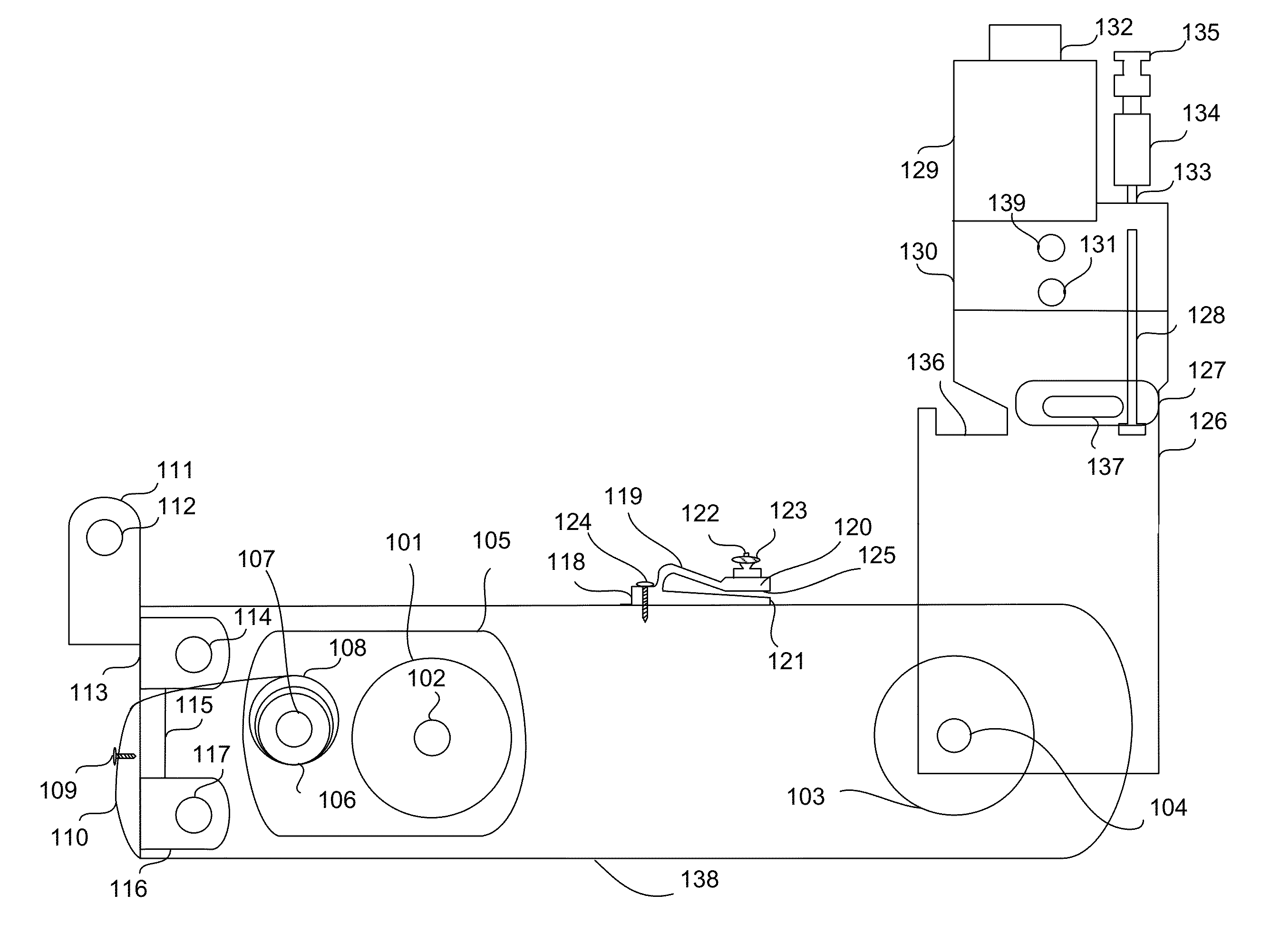
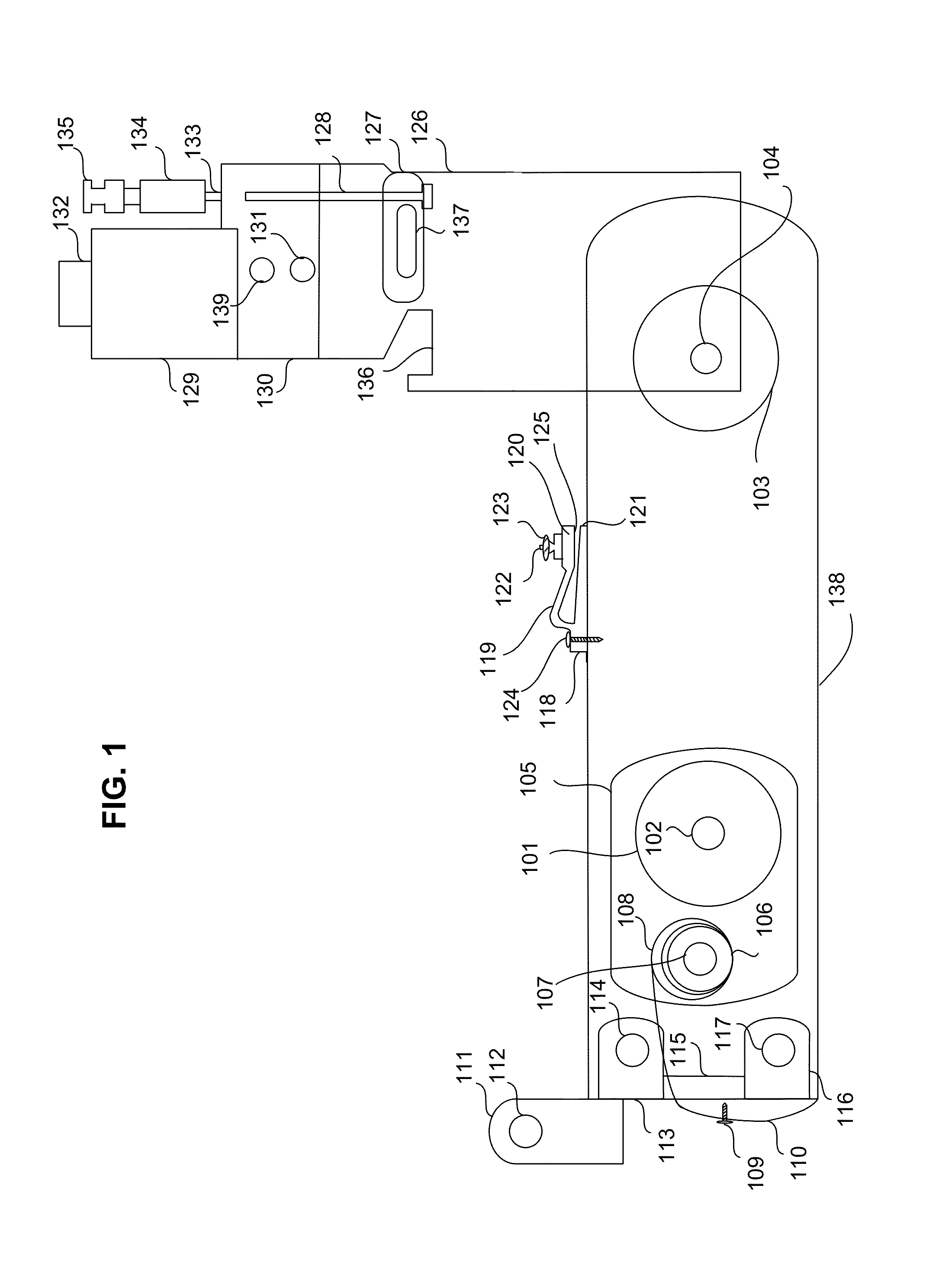
[0032]FIG. 1 is a cross sectional drawing illustrating a cable retractor that can be used with one or more embodiments of the speed control of the invention. The cable retractor of FIG. 1 comprises an articulate housing assembly comprising a cable stop housing 126 and a pulley housing 138. Cable stop housing 126 is pivotably coupled to pulley housing 138 such that cable stop housing 126 and pulley housing 138 can be rotated with respect to each other about an axis, for example, the first pulley axle 104 of first pulley set 103. Alternatively, a different axis than first pulley axle 104 of first pulley set 103 may be used to pivotably couple cable stop housing 126 to pulley housing 138.

[0033]A cable stop assembly 129 comprising a cable stop mechanism is coupled to the cable stop housing 126. Cable stop assembly 129 comprises a cable stop actuator button 132, which may be used to release the cable stop assembly 129 from frictionally detaining a cable 133 routed through cable stop asse...


PUM


Abstract

The present invention is a speed control for a cable retractor. The cable retractor with which the speed control is used comprises a pulley that engages a cable that may be extended and retracted. A friction element configured to adjustably contact the cable adjacent to the pulley is attached to a movable linkage. The movement of the linkage is constrained to move along a predetermined path such that movement of the linkage along the path alters the distance between the friction element and the pulley. In one or more embodiments a cantilevered spring is attached to the linkage. An adjustable control, for example a thumbscrew, is configured to move the spring in relation to the linkage in a manner that alters the position of the friction element with respect to the cable and / or the pressure exerted by the friction element on the cable.

Description

CROSS-REFERENCE TO RELATED APPLICATION[0001]This patent application is a continuation-in-part of U.S. patent application Ser. No. 12 / 795,611 filed Jun. 7, 2010, which claims the benefit of the filing date of U.S. Provisional Patent Application No. 61 / 186,346 filed Jun. 11, 2009, both of which are incorporated by reference in their entirety herein.BACKGROUND OF THE INVENTION[0002](1) Field of the Invention[0003]The present invention relates generally to mechanical apparatus for management of electrical cabling and, more specifically, to an adjustable speed control for a cable retractor that facilitates the controlled extension and retraction of cabling.[0004](2) Description of the Related Art[0005]Electronic equipment is typically interconnected by cables. Cables are often equipped with connectors that allow their connection to and disconnection from equipment. When cables are longer than necessary or are disconnected from equipment, they can be awkward and untidy.[0006]Prior art cab...

Claims


Application Information

Patent Timeline
IPC IPC(8): B65H75/44
CPCB65H75/4439B65H75/368B65H75/4421B65H2701/34H02G11/003
Inventor SOPER, MATTHEW
Owner RGB SYST INC
Why Eureka
Try Eureka