Method and device for lubricant oil transport in an internal combustion engine

a technology of internal combustion engine and lubricant oil, which is applied in the direction of lubrication of auxiliaries, pressure lubrication with lubrication pumps, oilsumps, etc., can solve the problems of affecting the efficiency of lubricant oil supply, interrupting lubricant circulation, and cost-intensive pumps that are additionally integrated into the internal combustion engin

Inactive Publication Date: 2005-11-17
IAV INGGES AUTO & VERKEHR
View PDF1 Cites 3 Cited by
  • Summary
  • Abstract
  • Description
  • Claims
  • Application Information

AI Technical Summary

Benefits of technology

[0014] It is an object of the present invention to provide a device and a method that assure the availability of the lubricant oil supply of an internal combustion engine using a wet sump and installed transversally in the simplest possible manner and without additional moving components, in the case of severe transverse acceleration and / or inclination. In addition, it is an object of the present invention to provide a device and a method which maintains both the required minimum distance of the oil pan from the road surface and a low center of gravity of the internal combustion engine.
[0025] This arrangement has the advantage that the lubricant oil supply of a transversally installed internal combustion engine using wet sump lubrication is assured in the case of severe transverse acceleration and / or inclination, without pumps additionally integrated into the internal combustion engine, which increase the costs and the failure likelihood of the internal combustion engine. Furthermore, the oil pan can be designed to have a flat construction, which allows a low center of gravity of the internal combustion engine while maintaining the required minimum distance of the oil pan from the road surface. With regard to the lubricant oil change intervals, it is furthermore advantageous that a higher lubricant oil level and therefore a greater amount of lubricant oil can be used, while maintaining the proportions of the oil pan. These features are possible because the lubricant oil, in which air is entrained due to the contact of the crank mechanism with the lubricant oil, is transported into an oil pan area where no contact of the crank mechanism with lubricant occurs. In this area of the oil pan, the oil can separate from the entrained air.

Problems solved by technology

It is known that in the case of transverse installation into a motor vehicle of an internal combustion engine using wet sump lubrication, the lubricant oil supply is problematic when severe transverse acceleration, inclination, or both occurs.
Thus, a risk exists that the central suction system will draw air in, instead of lubricant oil, and thereby interrupt lubricant circulation.
Pumps that are additionally integrated into an internal combustion engine are cost-intensive and increase the failure probability of the internal combustion engine.
This prevention, however, lasts only for a short period of time, as a result of the delayed equalization of the lubricant oil between the individual chambers.
Uniform lubricant oil transport in all the inclination states of the internal combustion engine cannot be expected, because not all the rotating parts are in contact with the lubricant oil at the same time.
However, this possibility requires an undesirable elevation of the center of gravity of the internal combustion engine, due to the required minimum distance of the oil pan from the road surface.

Method used


Image

  • Method and device for lubricant oil transport in an internal combustion engine
  • Method and device for lubricant oil transport in an internal combustion engine
  • Method and device for lubricant oil transport in an internal combustion engine

Examples


Embodiment Construction

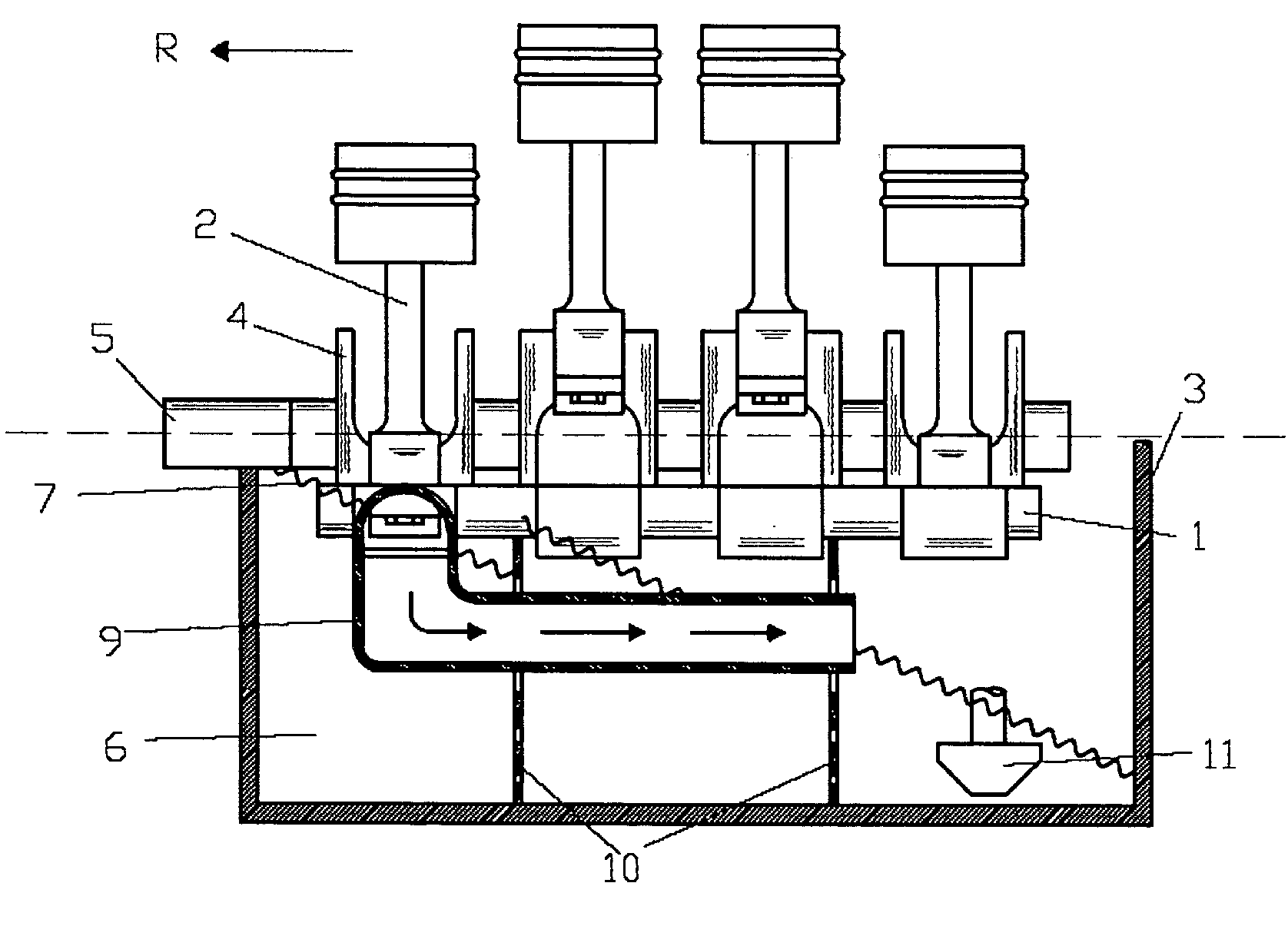
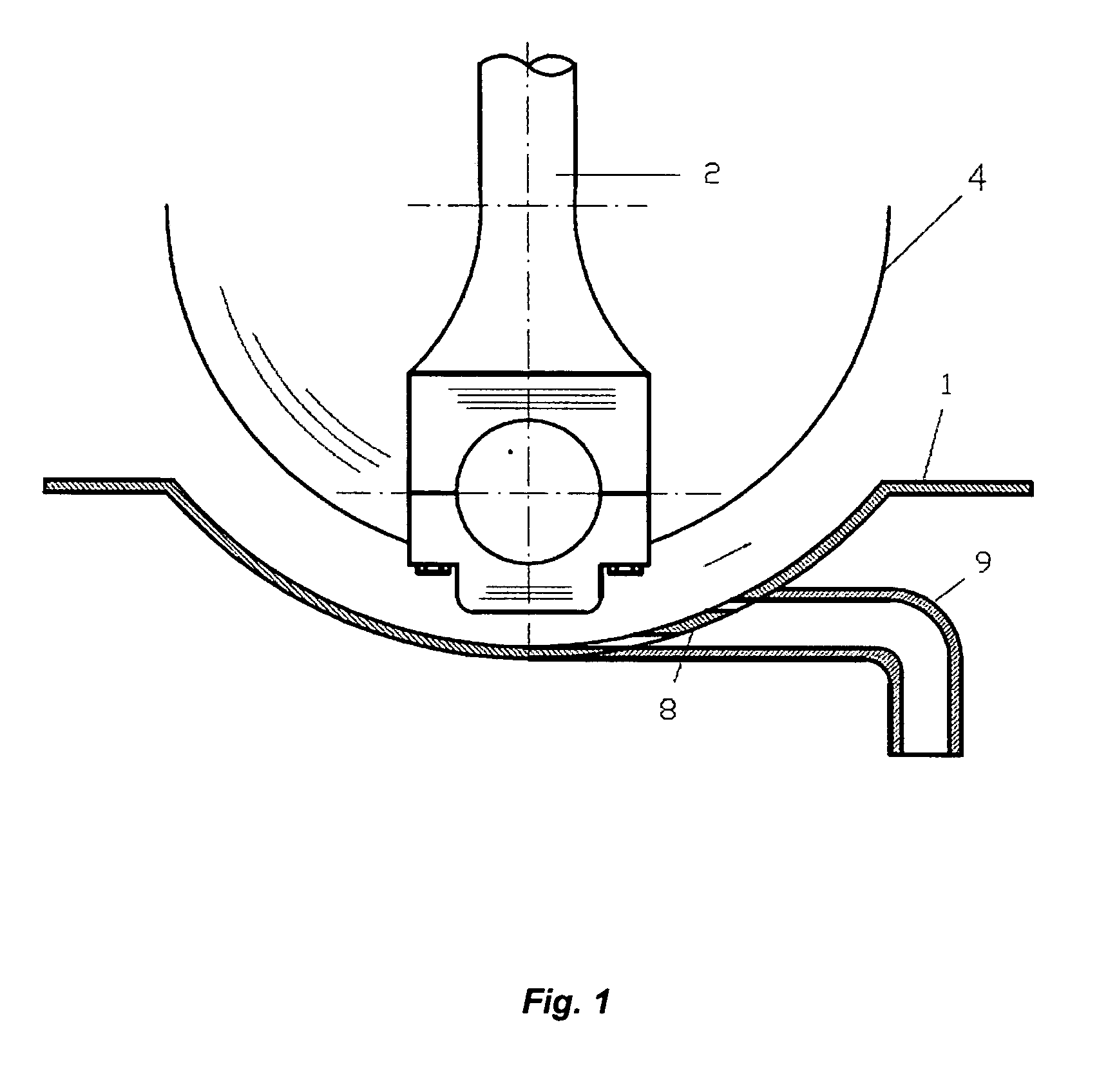
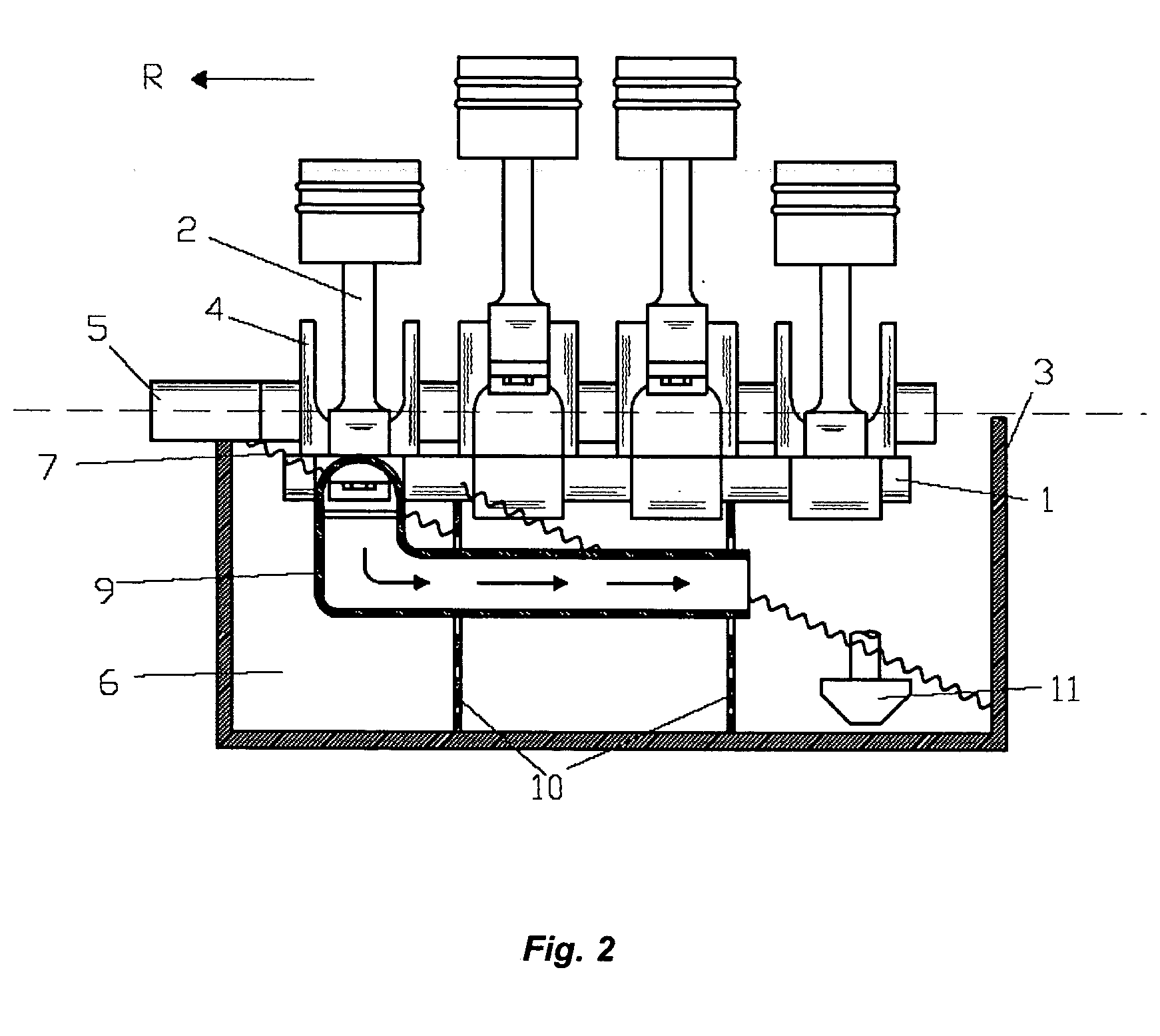
[0033] Referring now to the drawings, FIG. 2 shows an oil repulsion part 1 integrated into an internal combustion engine 3. A connecting rod 2 and crankshaft cheeks 4 are disposed on the outside in the direction of the transverse acceleration and / or inclination R. The direction of the transverse acceleration relating to the present invention means the direction of the centrifugal acceleration which is directed against the centripetal acceleration. Oil repulsion part 1 is configured, in the region of connecting rod 2 and crankshaft cheeks 4 so that a centrifugal flow, resulting from the interaction of oil repulsion part 1, connecting rod 2, and crankshaft cheeks 4 is brought about. This centrifugal flow is used for transport of the lubricant oil into the region of an oil pan 6 that lies opposite the transverse acceleration and / or inclination. A lubricant oil suction system 11 is disposed in this region of oil pan 6.

[0034] An oil repulsion part 1 of the type shown in FIGS. 1 to 4, in...


PUM


Abstract

A lubricant oil transport device and method is provided in an internal combustion engine using wet sump lubrication. Near the connecting rod and the crankshaft cheeks, which are disposed exteriorly in the transverse acceleration and / or inclination direction and lie opposite a decentralized oil suction system, the oil repulsion part is configured to cause a centrifugal flow for oil transport in the oil pan area opposite the transverse acceleration and / or inclination, resulting from interaction of the oil repulsion part, connecting rod, and crankshaft cheeks. Thus, lubricant oil supply is always assured, without pumps additionally integrated into the engine, which increase costs and likelihood of failure. The oil pan may also now be flatter, which allows a low center of gravity of the engine while maintaining the required minimum road surface distance. Regarding oil change intervals, a greater amount of oil can be used, with the same proportions of the oil pan.

Description

BACKGROUND OF THE INVENTION CROSS REFERENCE TO RELATED APPLICATIONS [0001] Applicant claims priority under 35 U.S.C. §119 of German Application No. 10 2004 024 780.3 filed May 17, 2004. [0002] 1. Field of the Invention [0003] The present invention relates to a method and a device for lubricant oil transport in an internal combustion engine using wet sump lubrication. [0004] 2. The Prior Art [0005] It is known that in the case of transverse installation into a motor vehicle of an internal combustion engine using wet sump lubrication, the lubricant oil supply is problematic when severe transverse acceleration, inclination, or both occurs. The central suction system is disposed deep in the wet sump and is connected with the lubricant pump. Thus, a risk exists that the central suction system will draw air in, instead of lubricant oil, and thereby interrupt lubricant circulation. [0006] To improve the reliability of the lubricant oil supply in case of severe transverse acceleration and / o...

Claims


Application Information

Patent Timeline
Patent Type & Authority Applications(United States)
IPC IPC(8): F01M1/04F01M11/00F01M11/06
CPCF01M11/0004F01M2011/0041F01M11/064
Inventor STADTAUS, FRANK
Owner IAV INGGES AUTO & VERKEHR
Why Eureka
Try Eureka