Solid state spot light assembly

Active Publication Date: 2011-10-20
ELUMIGEN
View PDF8 Cites 4 Cited by
  • Summary
  • Abstract
  • Description
  • Claims
  • Application Information

AI Technical Summary

Benefits of technology

[0007]The present disclosure provides a lighting assembly that is used for generating light and providing a long-lasting and thus cost-effective unit.

Problems solved by technology

However, the materials used in compact fluorescent bulbs are not environmentally friendly.
However, many compact fluorescent bulbs and light-emitting diode lights do not have the same light spectrum as incandescent bulbs.
They are also relatively expensive.
In many known configurations, light-emitting diode lights are subject to premature failure due to heat and light output deterrents with increased temperature.

Method used


Image

  • Solid state spot light assembly
  • Solid state spot light assembly
  • Solid state spot light assembly

Examples


Embodiment Construction

[0057]The following description is merely exemplary in nature and is not intended to limit the present disclosure, application, or uses. For purposes of clarity, the same reference numbers will be used in the drawings to identify similar elements. As used herein, the phrase “at least one of A, B, and C” should be construed to mean a logical (A or B or C), using a non-exclusive logical OR. It should be understood that steps within a method may be executed in different order without altering the principles of the present disclosure.

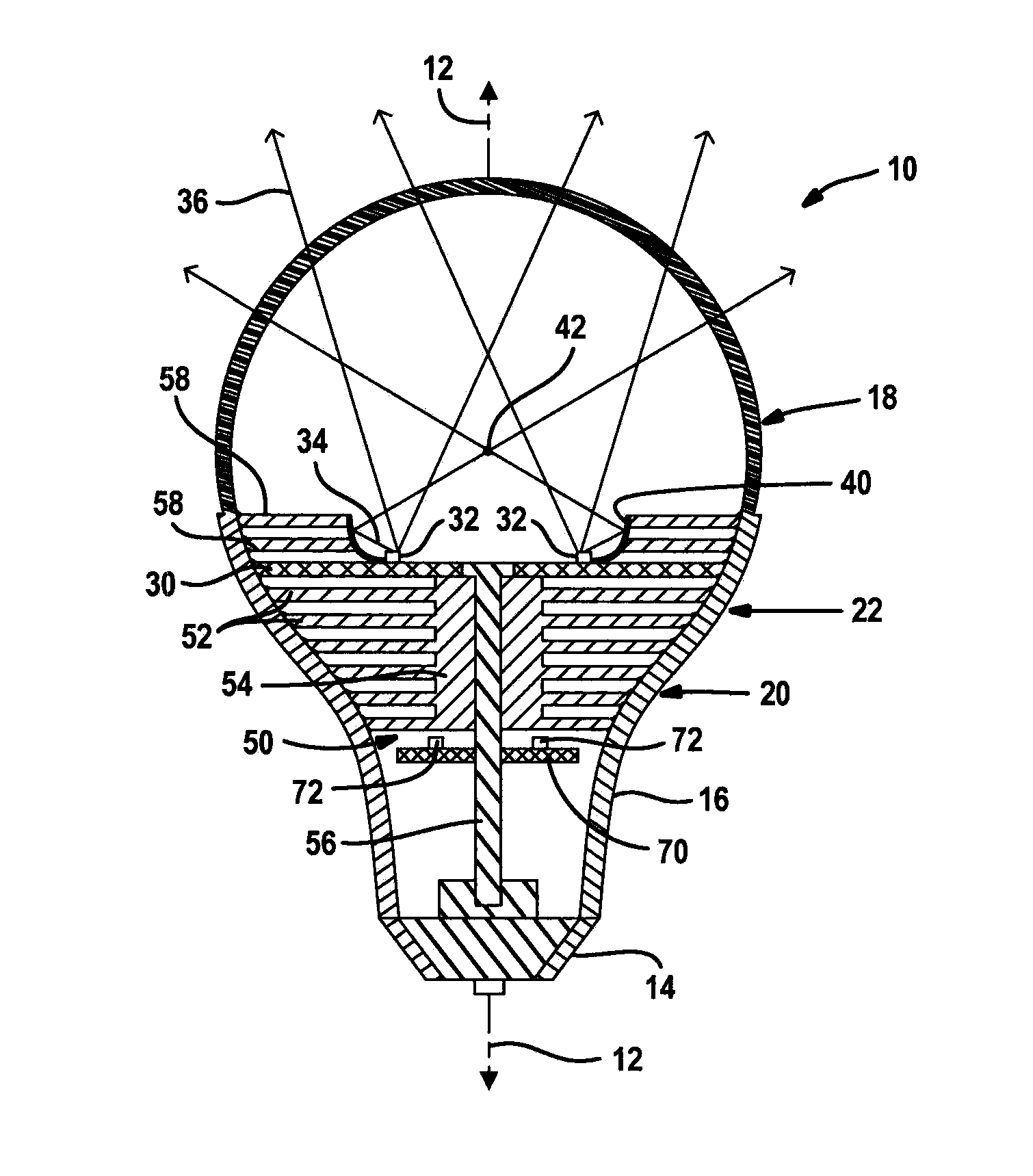
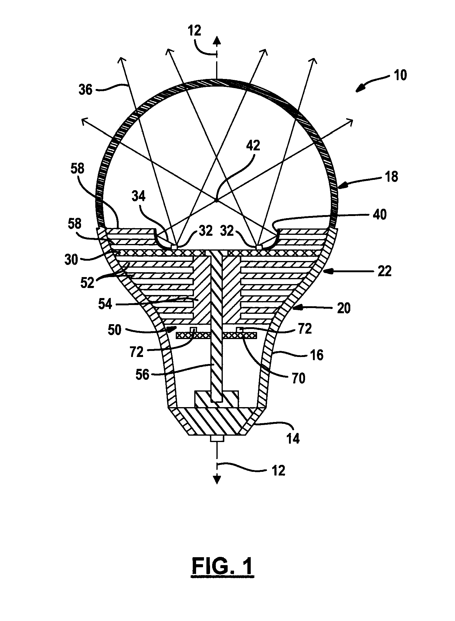
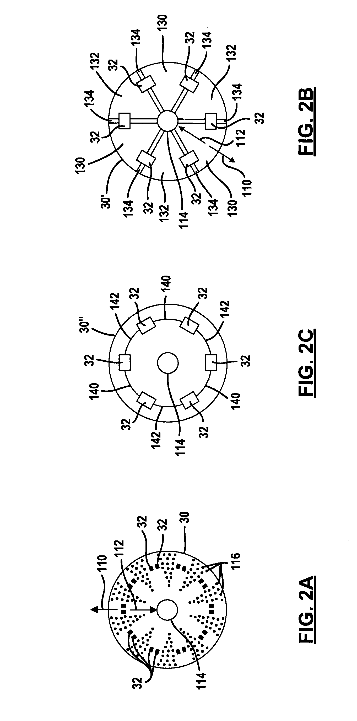
[0058]It should be noted that in the following figures various components may be used interchangeably. For example, several different embodiments of control circuit boards and light source circuit boards are implemented. As well, various shapes of light redirection elements and heat sinks are also disclosed. Various combinations of heat sinks, control circuit boards, light source circuit boards, and shapes of the light assemblies may be used. Various types ...


PUM

PropertyMeasurementUnit
Angleaaaaaaaaaa
Lightaaaaaaaaaa

Abstract

A light assembly that includes a base, a housing extending from the base having a partial paraboloidal cross-sectional surface, a light-shifting element disposed within the housing, and a plurality of light sources coupled to the housing. The light sources generate light. The light assembly also includes an angular portion reflecting light from the light sources toward the parabolic cross-sectional surface so that the light reflected from the parabolic surface is directed toward the light-shifting element and light reflected from the light-shifting element is directed out of the housing after reflecting from the housing.

Description

CROSS-REFERENCE TO RELATED APPLICATIONS[0001]This application is a continuation of U.S. patent application Ser. No. 12 / 817,807 filed on Jun. 17, 2010, which claims the benefit of U.S. Provisional Application Nos. 61 / 220,019, filed on Jun. 24, 2009 and 61 / 265,149, filed Nov. 30, 2009. The entire disclosures of each of the above applications are incorporated herein by reference.TECHNICAL FIELD[0002]The present disclosure relates generally to lighting using solid state light sources such as light-emitting diodes or lasers and, more specifically, to lighting devices for various applications that use conic sections and various structural relationships to provide an energy-efficient long-lasting life source.BACKGROUND[0003]This section provides background information related to the present disclosure which is not necessarily prior art.[0004]Providing alternative light sources is an important goal to reduce energy consumption. Alternatives to incandescent bulbs include compact fluorescent ...

Claims


Application Information

Patent Timeline
IPC IPC(8): F21V7/00F21V5/00
CPCF21K9/135F21K9/56F21V3/00F21V7/0025F21V29/767F21Y2101/02F21Y2103/022F21V7/22F21V29/75F21V7/08F21S2/00F21V7/06F21V23/003F21V13/00F21K9/232F21K9/64F21Y2103/33F21Y2115/10F21V3/02F21V9/35F21V9/30F21V13/08F21V9/08F21V9/06F21V7/28F21K9/20F21K9/60F21V7/00F21V19/0035F21Y2101/00F21V29/70F21V23/009
Inventor DASSANAYAKE, MAHENDRADE MEL, SRINISAMARABANDU, JAGATH
Owner ELUMIGEN
Why Eureka
Try Eureka