

Heat gun
- Summary
- Abstract
- Description
- Claims
- Application Information
AI Technical Summary
Benefits of technology
Problems solved by technology
Method used
Image

Examples
Embodiment Construction
[0012]The disclosure, including the accompanying drawings, is illustrated by way of example and not by way of limitation. It should be noted that references to “an” or “one” embodiment in this disclosure are not necessarily to the same embodiment, and such references mean at least one.
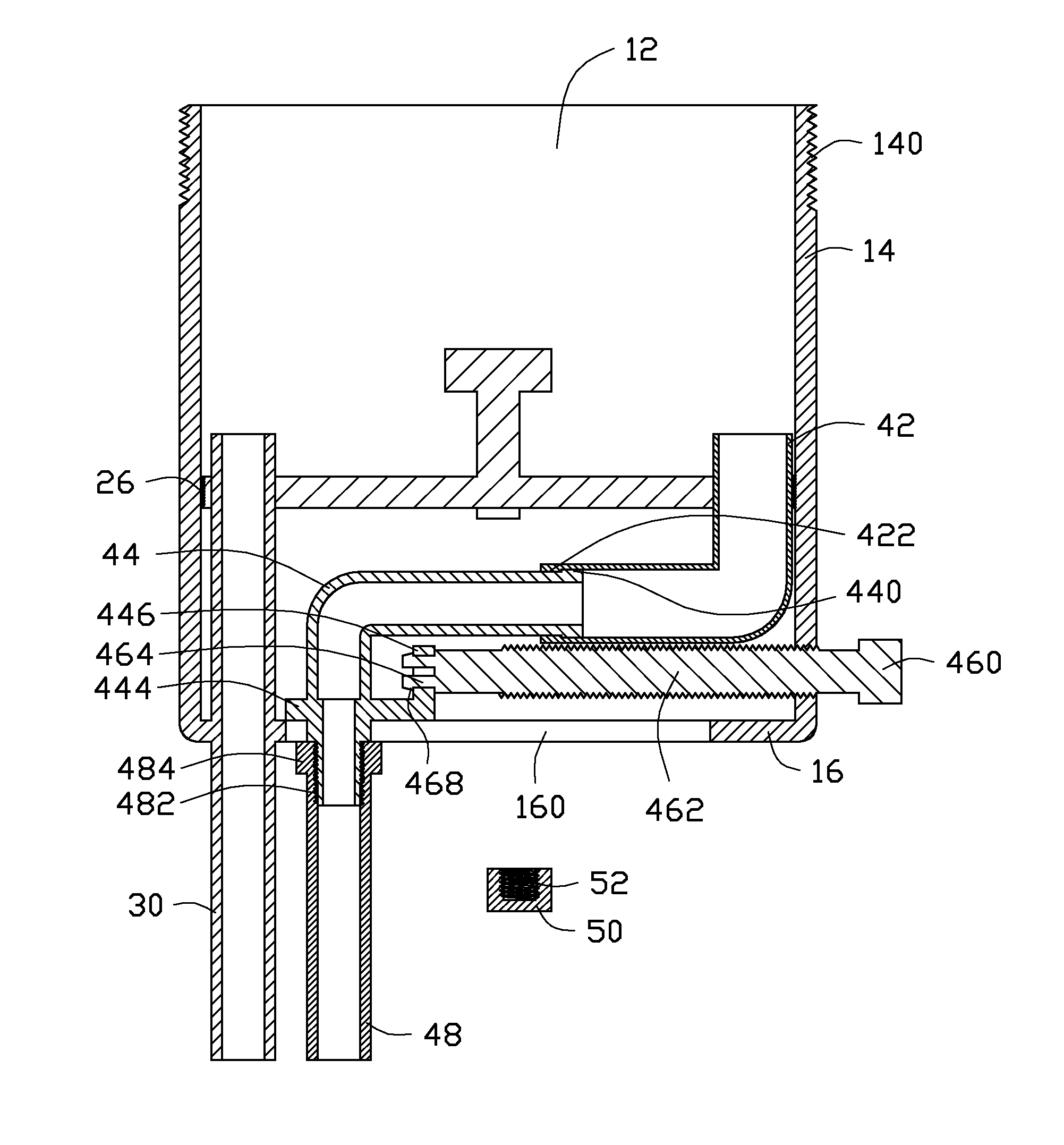
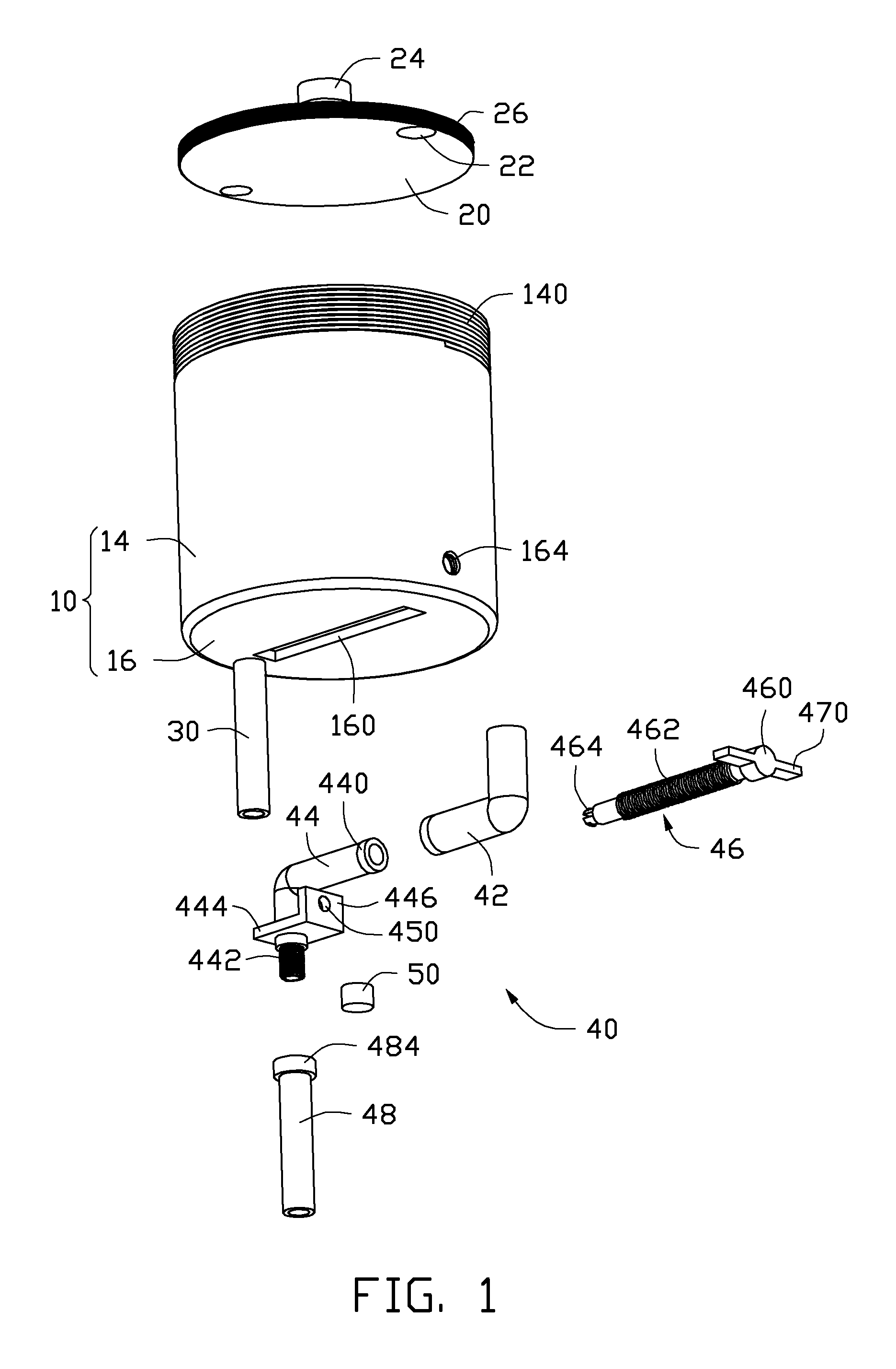
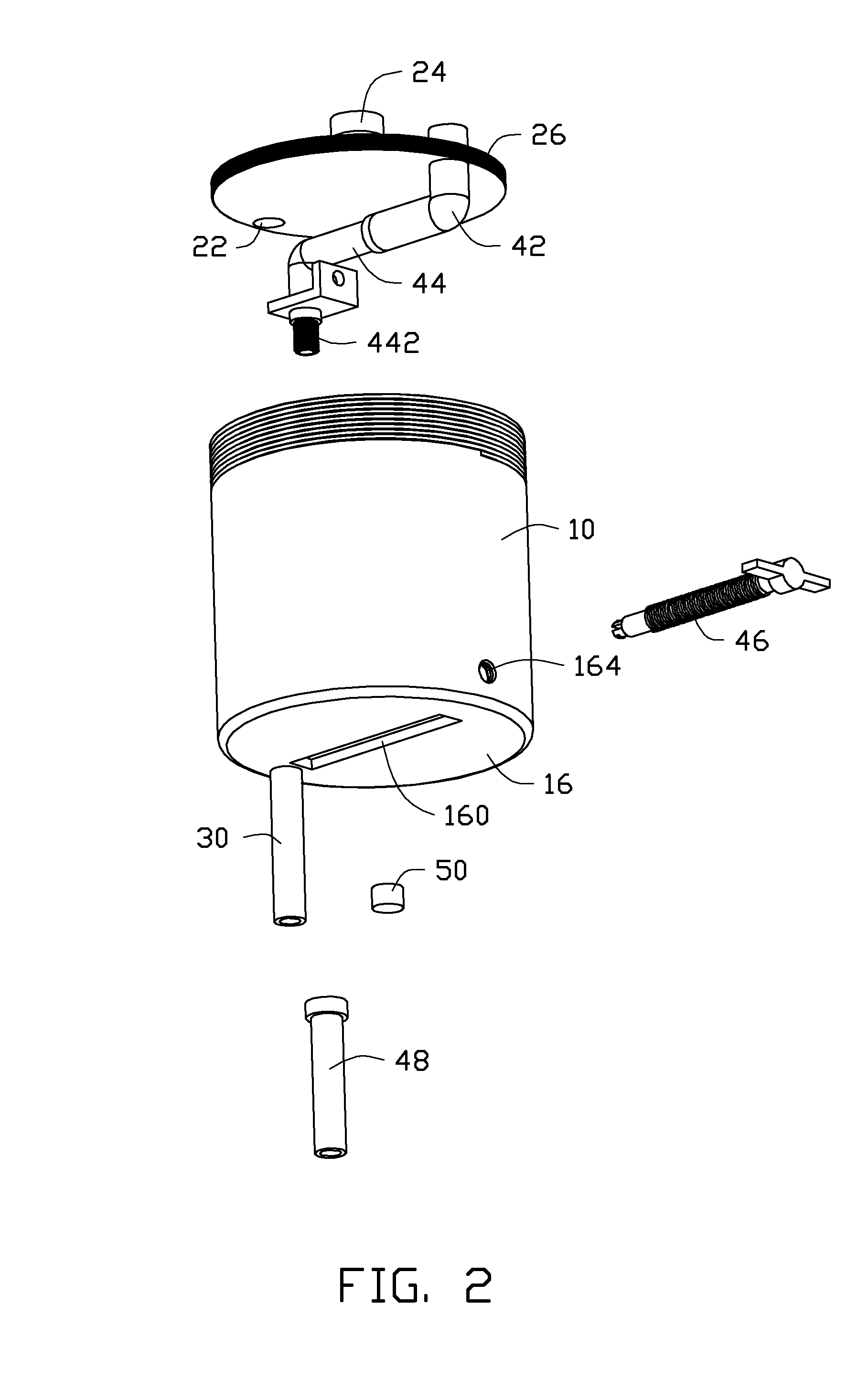
[0013]FIGS. 1 and 4 show an exemplary embodiment of a heat gun. The heat gun includes a hollow columnar canister 10, a round installation board 20, an outlet pipe 30, an assistant member 40, and a stopple 50.
[0014]The canister 10 defines a receiving space 12 extending through a top end of the canister 10. The canister 10 includes a columnar sidewall 14 bounding the receiving space 12, a cover (not shown) detachably installed to the top end of the canister 10, and a bottom wall 16 connected to and covering a bottom end of the canister 10. The bottom wall 16 defines a slot 160 in a middle of the bottom wall 16. The slot 160 communicates with the receiving space 12. The sidewall 14 defines a threaded hole...
PUM
| Property | Measurement | Unit |
|---|---|---|
| circumference | aaaaa | aaaaa |
| inner circumference | aaaaa | aaaaa |
| outer circumference | aaaaa | aaaaa |
Abstract
Description
Claims
Application Information