
Mechanism for transmitting power of rotation

a technology of transmission power and rotation, which is applied in the direction of mechanical equipment, belts/chains/gearrings, and gear elements, etc., can solve the problems of reducing the energy efficiency of transmission, limiting the torque that can be transmitted, and requiring chain stretching to achieve the adhesion of the chain to the conical surfa

Active Publication Date: 2014-06-12
CLOPET CYRIL +2
View PDF35 Cites 15 Cited by
  • Summary
  • Abstract
  • Description
  • Claims
  • Application Information

AI Technical Summary

Benefits of technology

The patent describes a transmission mechanism that uses a locking element to unify two parts, a link and a rotary element, and has the ability to self-unlock. The locking element is designed to roll on a surface, which reduces friction and allows for easier movement of the parts. The mechanism includes a force transmitting connecting element that increases with the torque transmitted and is designed to ensure adhesion by static friction. Self-locking means are also included to maintain the locking element in a disengaged state. The technical effects of this transmission mechanism include high torque transmission, good energy efficiency, and self-unlocking.

Problems solved by technology

This limits the torque that can be transmitted.
Moreover, the energy consumed in compressing the springs and releasing the pressure greatly reduces the energy efficiency of the transmission.
However, there is a drawback to such transmission in that adhesion of the chain to the conical surfaces requires that the chain be stretched, not only in its “stretched” strand but also in its “slack” strand.
The chain must be subject to a basic tension that is not used to transmit torque and brings about multiple parasitic sources of friction.
The energy efficiency is very mediocre.
This transmission also had mediocre efficiency because the compression and release of the elastic supports of each link consumes energy.

Method used


Image

  • Mechanism for transmitting power of rotation
  • Mechanism for transmitting power of rotation
  • Mechanism for transmitting power of rotation

Examples


Embodiment Construction

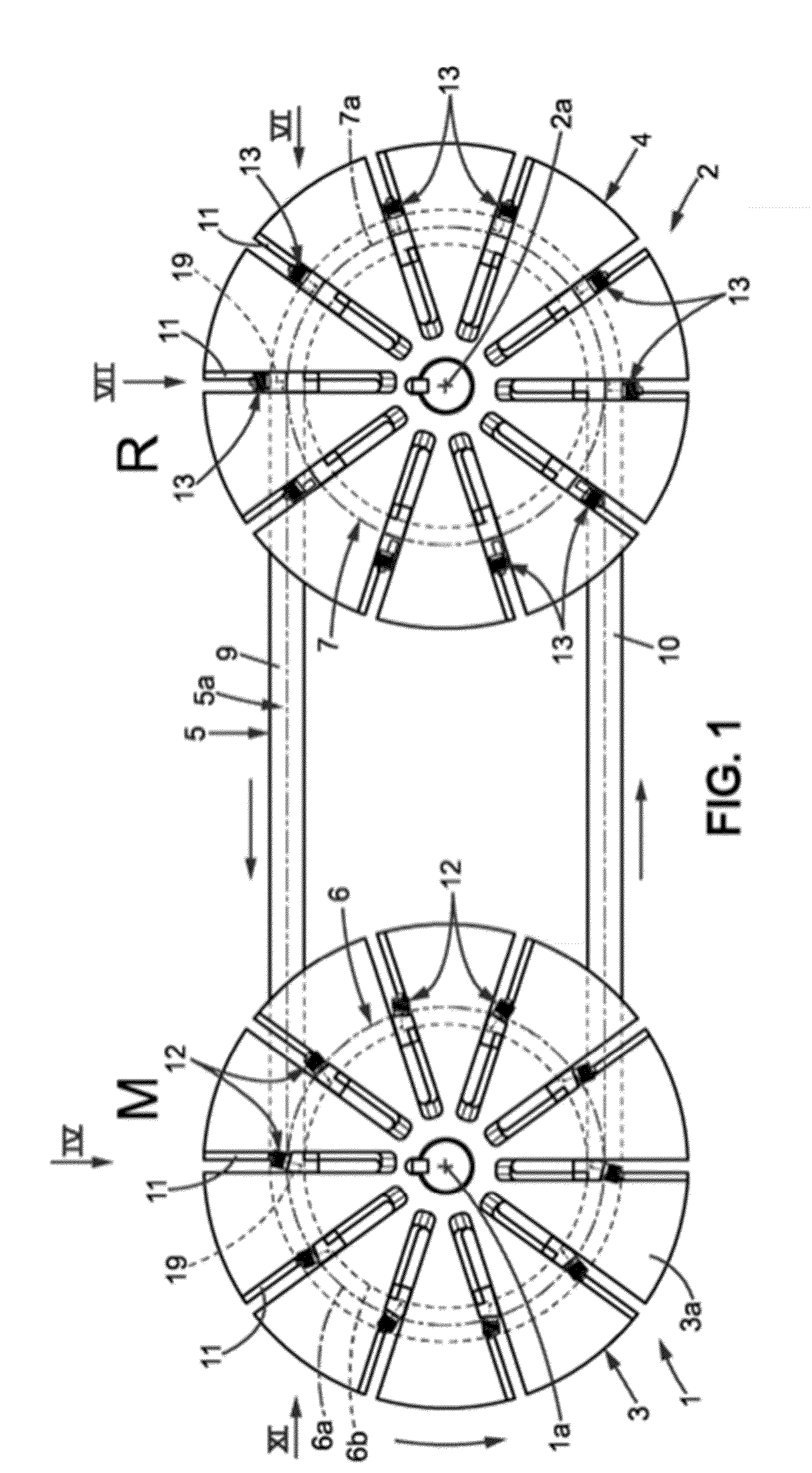
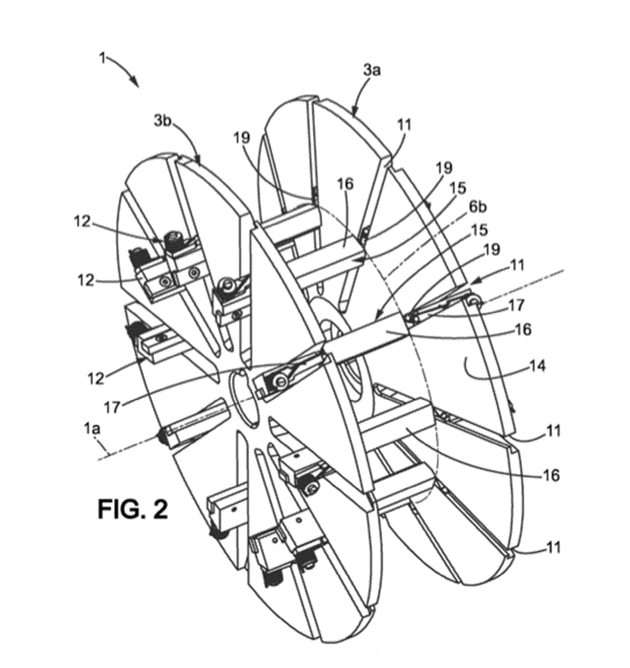
[0108]Using FIGS. 1 to 13, we shall describe a first family of embodiments, in which the ability of self-locking means to self-unlock whenever said means leaves the active portion of the drive circle, exploits the fact that, whenever a link portion passes from a circular portion to an appreciably rectilinear portion of its trajectory, it is straightened. This straightening is accompanied primarily by a relative movement of said link portion with respect to the immediately upstream portion. This small relative movement is employed to unlock the locking element.

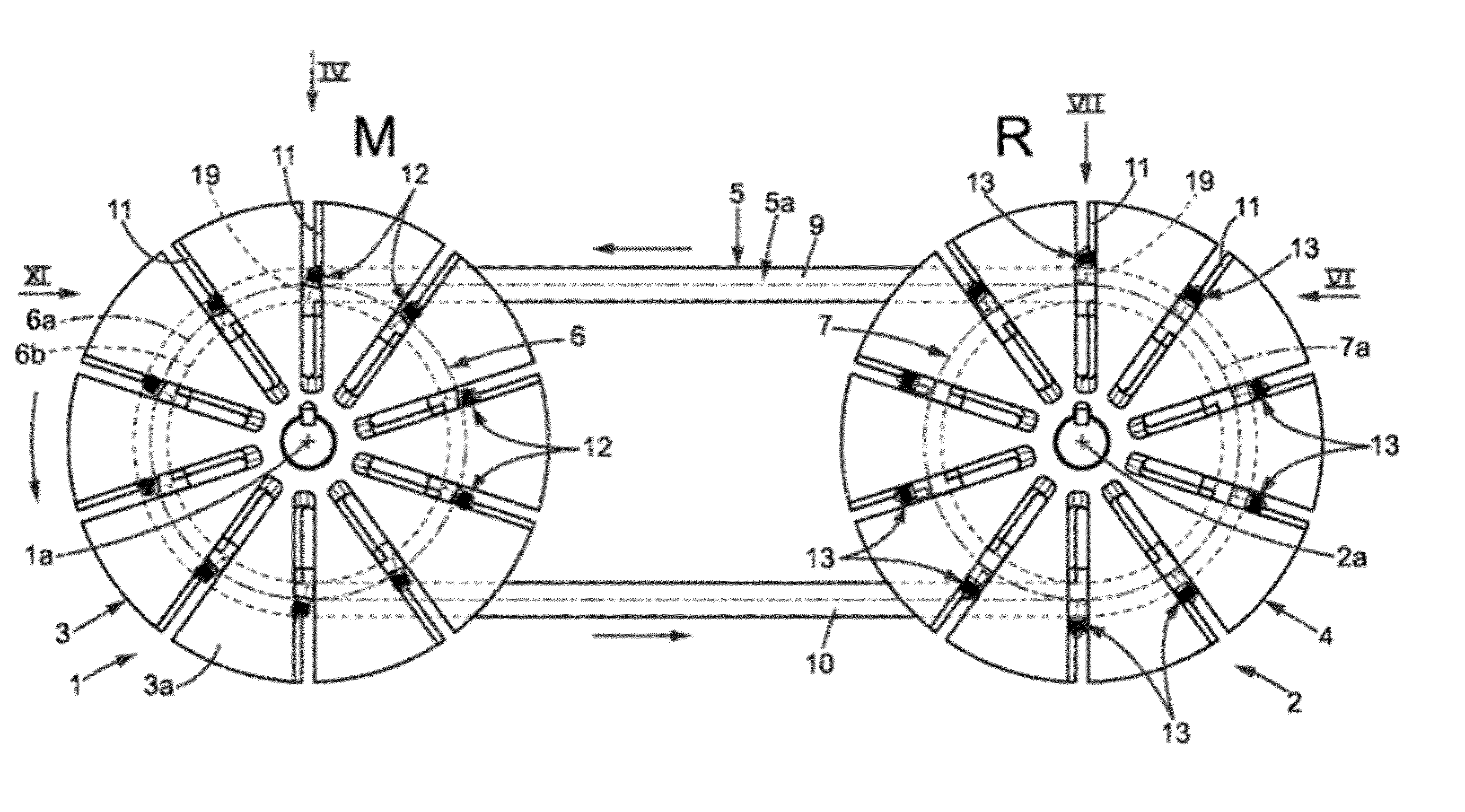
[0109]As illustrated in FIG. 1, transmission comprises a first driving rotary element, 1, and a second receiving rotary element, 2, rotationally mobile around a first driving axis, 1a, and a second receiving axis, 2a, respectively. Driving rotary element 1 comprises a pair of driving wheels, 3, and receiving rotary element 2 comprises a pair of receiving wheels, 4. The transmission also comprises a link, 5, surrounding driving ...


PUM


Abstract

A mechanism for transmitting rotational power comprising: a link extending along a closed loop and continued by a succession of portions each having a longitudinal direction tangent to the closed loop; and temporary unification means comprising a plurality of self-locking means distributed at least along an active portion of a first drive circle, and comprising at least one rigid locking element simultaneously pressing against a first support surface of the first rotating element and a second support surface of a link portion facing the locking element. The first and second support surfaces are arranged so that one locking element of the first drive circle active portion is jammed between the support surfaces and is capable of self-unlocking when the corresponding self-locking means leaves the active portion. One of the support surfaces is a tangential gripping surface that is parallel to the longitudinal direction of the link portion against which the locking element presses.

Description

FIELD OF THE INVENTION[0001]The invention concerns the field of mechanisms for transmitting mechanical power between two rotating elements. The invention notably concerns mechanisms able to continuously vary the ratio of rotational speed. Such transmission systems are known as “continuously variable transmissions” (CVT).STATE OF THE ART[0002]In 1935, application GB 436,053 described a speed changing mechanism that used a chain connecting two shafts. On each shaft is mounted a wheel equipped with sectors, each of which is mounted on a spring so that they press against the chain. When the chain links have gone around the wheel and are about to connect to the other wheel, the release of the links requires that the pressure be released by successively compressing the sector springs. In this mechanism, the circular trajectory of the chain is maintained solely by the pressure against the sides of the chain. Thus, the pressure force must be very high to prevent the chain from slipping on t...

Claims


Application Information

Patent Timeline
Patent Type & Authority Applications(United States)
IPC IPC(8): F16H9/10
CPCF16H9/10F16H9/24F16H55/54
Inventor CLOPET, CYRILAZZOPARDI, PIERRE ALAINREVOL, VINCENT
Owner CLOPET CYRIL
Learn More