

Pivotal Unit For Barbell
- Summary
- Abstract
- Description
- Claims
- Application Information
AI Technical Summary
Benefits of technology
Problems solved by technology
Method used
Image

Examples
Embodiment Construction
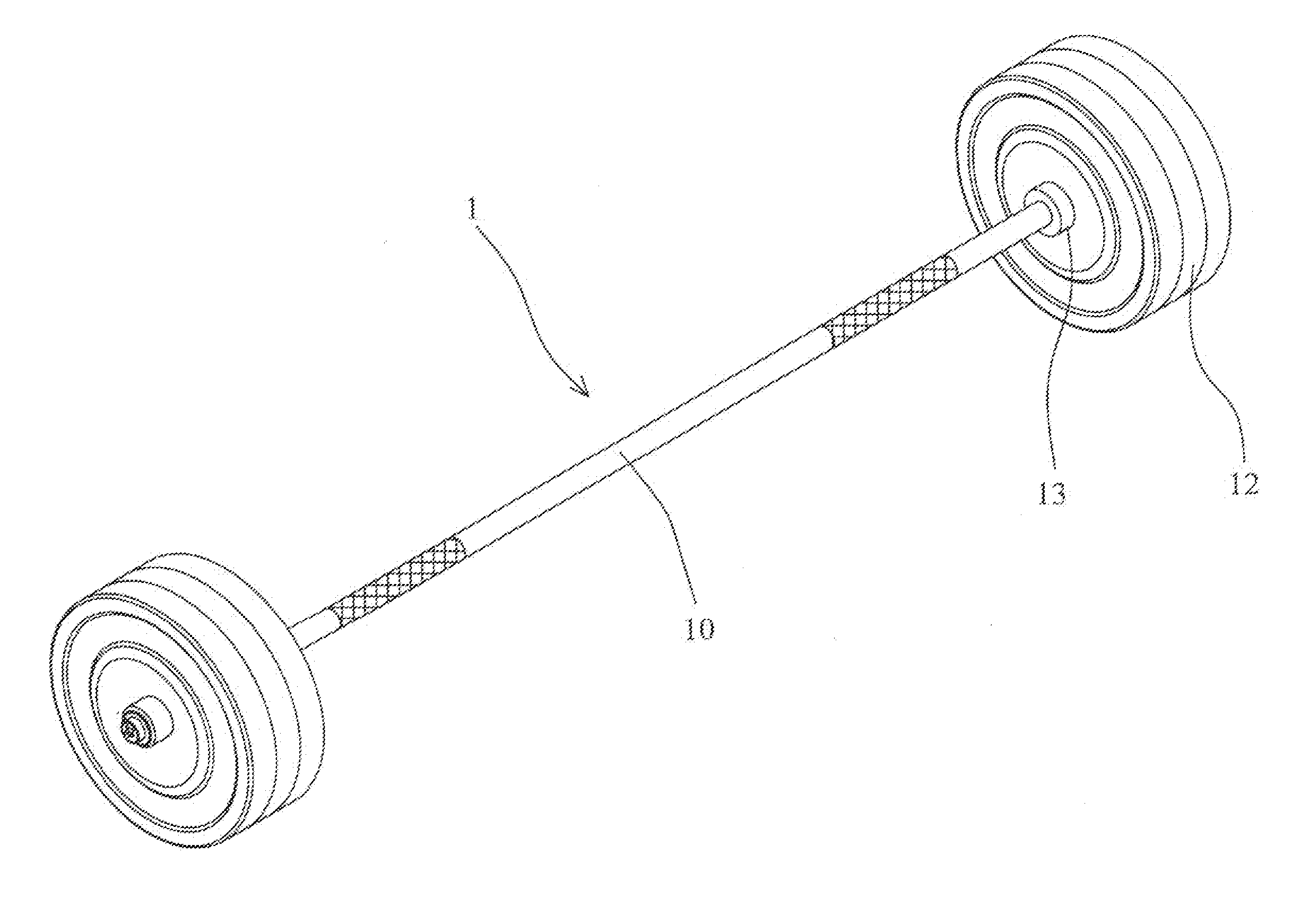
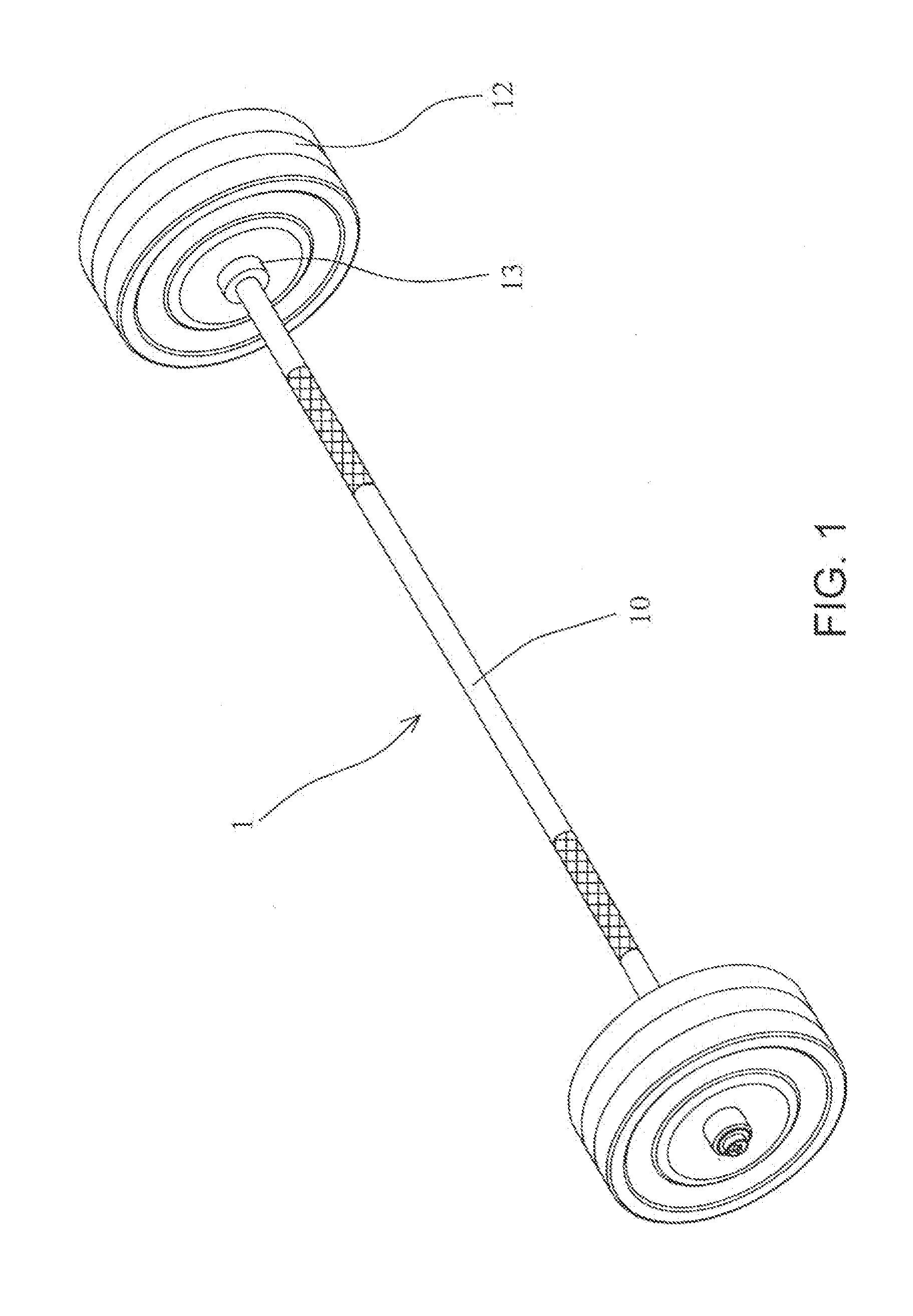
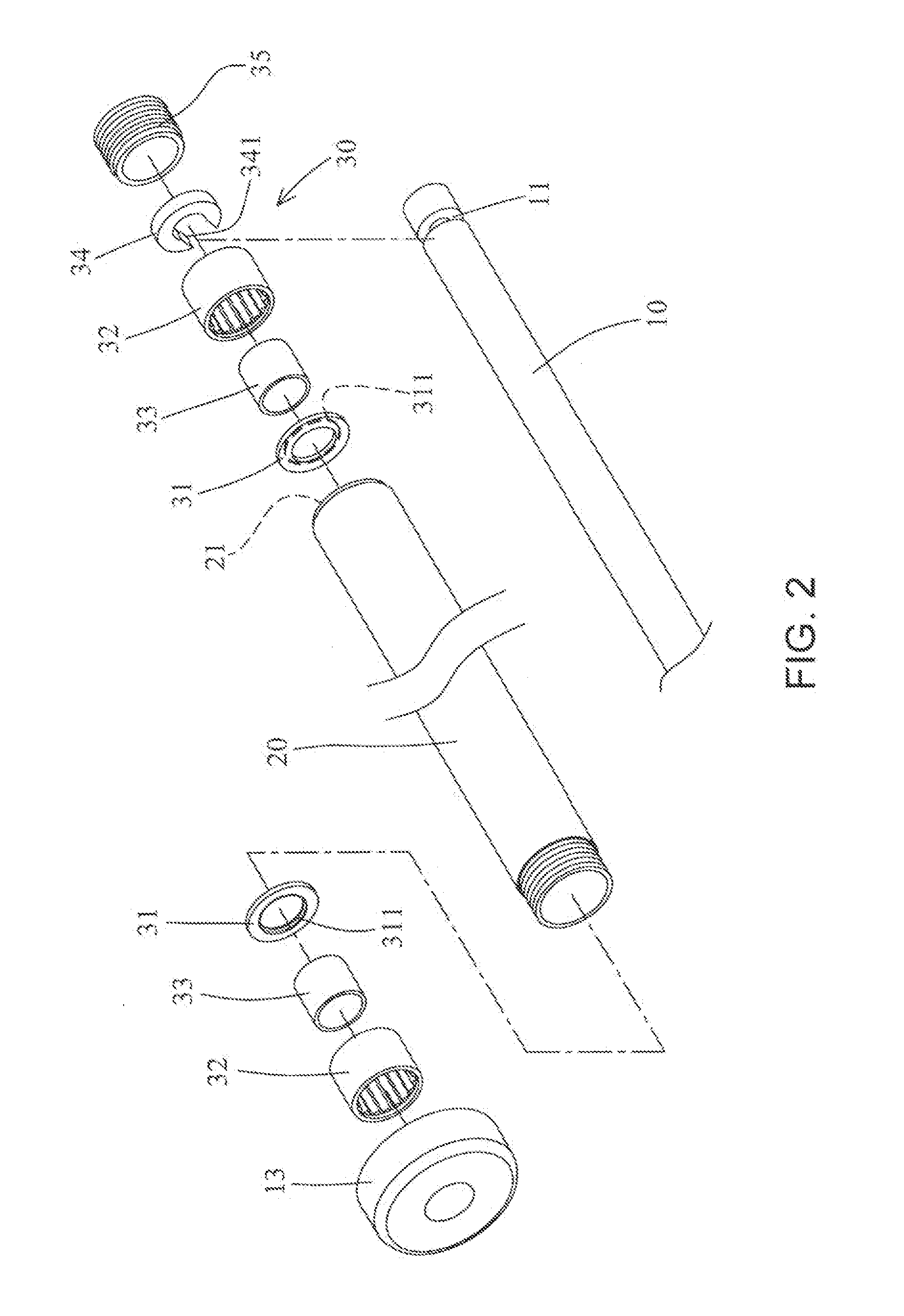
[0021]Referring to FIGS. 1 to 3, the barbell 1 of the present invention comprises a rod 10 with proper flexibility and two grooves 11 are respectively defined in two ends of the rod 10. Two tubular members 20 are respectively mounted to the two ends of the rod 10 and the weights 12 are mounted to the tubular members 20. Each tubular member 20 has two open ends 21 and a stop 13 is connected to the end away from the distal end of the rod 10 so as to position the weights 12.
[0022]Two pivotal units 30 are respectively located in the two tubular members 20 and mounted to the two ends of the rod 10. Each pivotal unit 30 has a washer 31, a bearing 32, a sleeve 33, a positioning member 34 and an end piece 35. The rod 10 extends through the two tubular members 20 and a shoulder 22 is formed in the inner periphery of each of the two open ends 21 of the tubular member 20. The washer 31 has a recess 311 defined in one side thereof. The bearing 32 is securely connected to the inside of the tubul...
PUM
 Abstract
Description
Claims
Application Information