
Method of manufacturing an engine block

Active Publication Date: 2014-06-19
CATERPILLAR INC
View PDF0 Cites 1 Cited by
  • Summary
  • Abstract
  • Description
  • Claims
  • Application Information

AI Technical Summary

Benefits of technology

The patent describes a method for making an engine block by removing material from the top deck of the block and creating a cavity around certain openings. A seal is then placed around the openings and an insert is positioned within the cavity. This method allows for the replacement of certain parts of the engine block without needing to replace the entire block. The patent also describes a kit for remanufacturing the engine block, which includes various inserts and seals for positioning within the recessed areas around the openings. Overall, this patent provides a cost-effective and efficient way to reuse and upgrade certain parts of an engine block.

Problems solved by technology

Many components of an internal combustion engine are subject to high loads and wear during operation of the engine.
These events may subject the engine block to high loads and stresses, including thermal stresses and mechanical stresses, which may be transmitted to the engine block at, among other locations, the cylinder head, which is mounted to a top deck of the engine block, and the cylinder bores.
As a result of these stresses, small cracks may form, or general wear may occur, within the engine block, particularly within or near the cylinder bores at the top deck of the engine block.
In addition, wear and erosion may occur along edges of fluid passages surrounding the cylinder bores and opening through the top deck.
Although the described method may adequately repair cracks occurring within the cylinder bore, the reference does not contemplate cracks that may radiate from the cylinder bore and across the top deck of the engine block, or that may occur along edges of the surrounding water passages.
Nor does the method address providing sealing for a relatively shallow insert.

Method used


Image

  • Method of manufacturing an engine block
  • Method of manufacturing an engine block
  • Method of manufacturing an engine block

Examples


Embodiment Construction

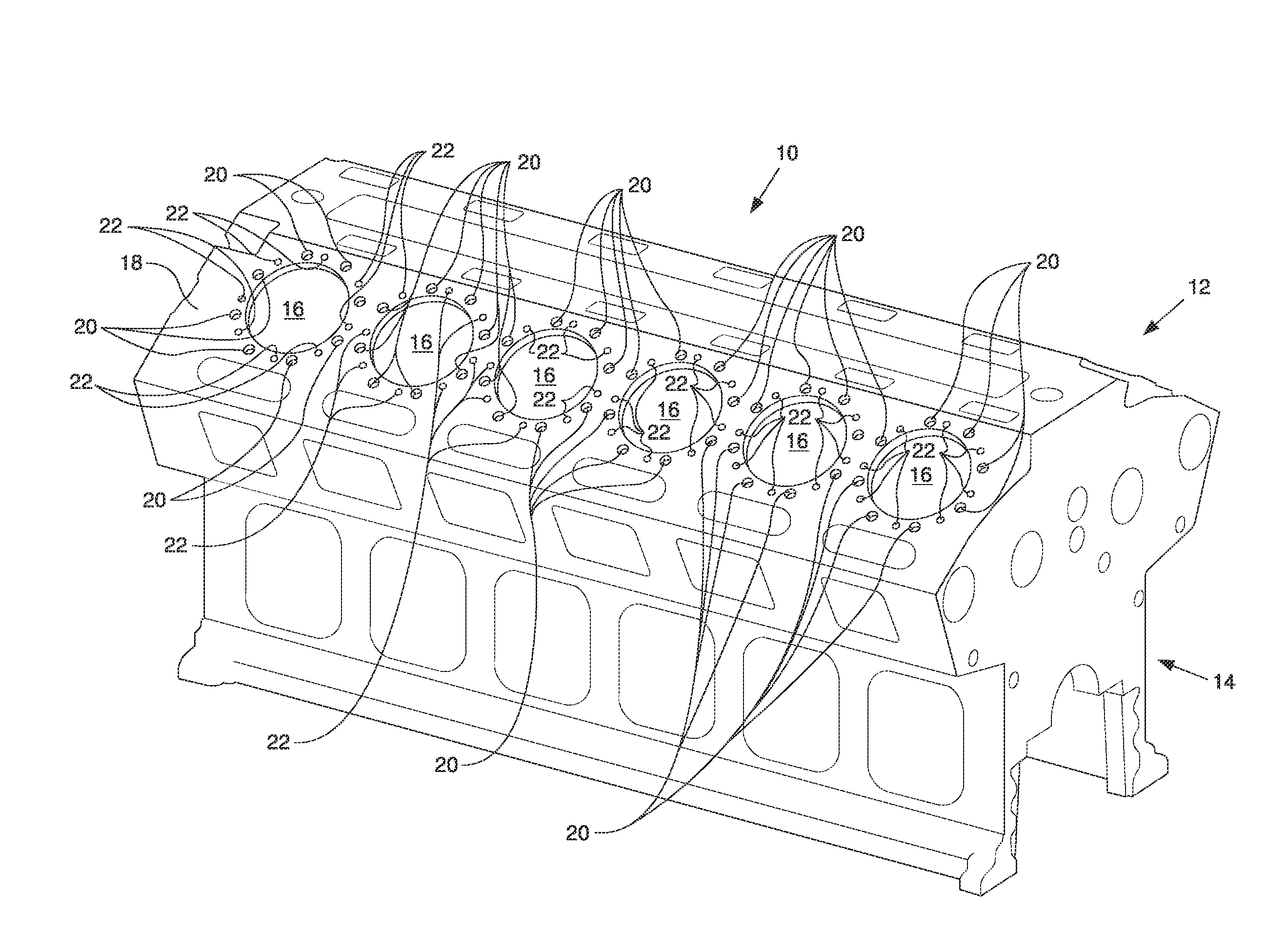
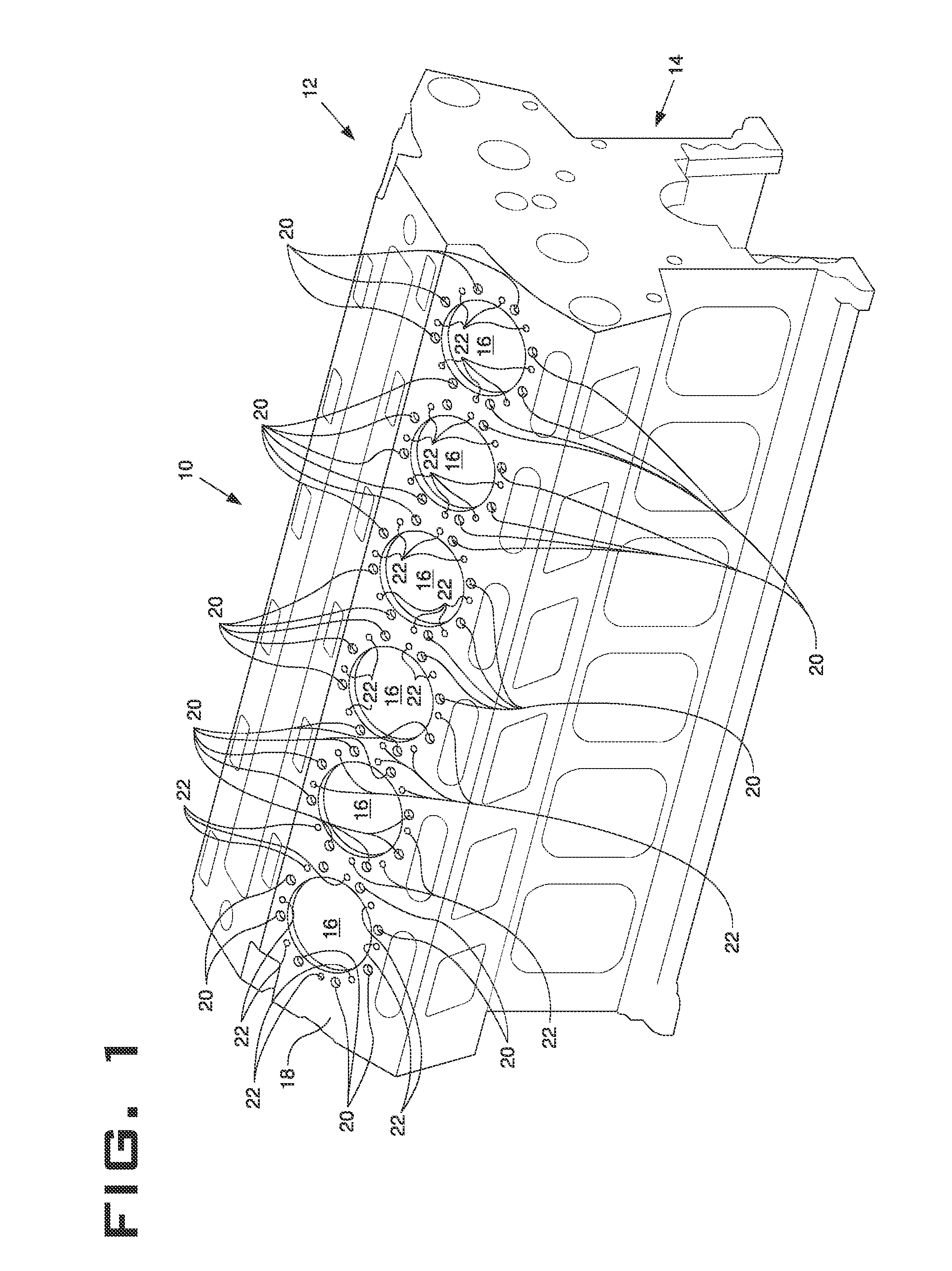
[0018]An exemplary embodiment of an engine block 10, also referred to as a cylinder block, is shown generally in FIG. 1. The engine block 10 may, for example, be constructed of cast iron or, alternatively, aluminum or magnesium, or any other desirable material, and may include one or more cylindrically bored holes for receiving pistons of an internal combustion engine, such as a compression ignition engine or a spark-ignited engine. It should be appreciated that such an internal combustion engine, which includes engine block 10, may be used to power an on-highway or off-highway machine, stationary equipment, or any other known machine or vehicle.

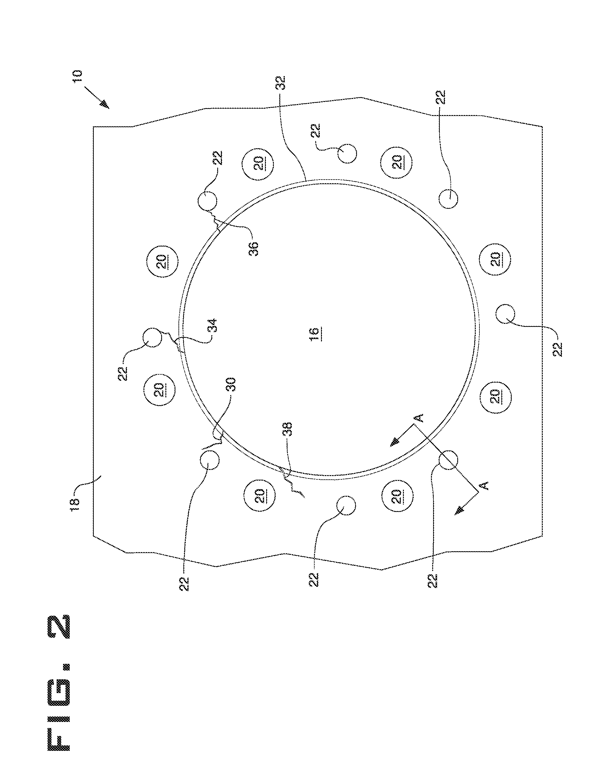
[0019]The engine block 10 may be a one-piece casting and may generally include an upper section 12 and a lower section 14. The upper section 12 of the engine block 10 may include a variety of openings, such as cylinder bores, fluid passages, and attachment bores. In the depicted embodiment, the upper section 12 may include a plurality of cyl...


PUM

PropertyMeasurementUnit
Fractionaaaaaaaaaa
Diameteraaaaaaaaaa
Areaaaaaaaaaaa

Abstract

A method for manufacturing an engine block includes removing material from the top deck of the engine block surrounding a first opening to create a first recessed area, placing a first seal within the first recessed area, positioning a first insert within the first recessed area and against the first seal. The method may also include removing material from the top deck of the engine block surrounding a second opening to create a second recessed area that at least partially overlaps the first recessed area, placing a second seal in the second recessed area and positioning a second insert within the second recessed area and against the second seal.

Description

TECHNICAL FIELD[0001]The present disclosure relates generally to a method of manufacturing an engine block. More particularly, the present disclosure relates to remanufacturing an engine block by removing material from the top deck surrounding a plurality of openings and positioning seals and inserts in the recessed areas.BACKGROUND[0002]Many components of an internal combustion engine are subject to high loads and wear during operation of the engine. One such component, for example, is the engine block, which may experience loads from combustion events occurring within combustion chambers formed by the cylinder head, pistons, and cylinder bores of the engine block. These events may subject the engine block to high loads and stresses, including thermal stresses and mechanical stresses, which may be transmitted to the engine block at, among other locations, the cylinder head, which is mounted to a top deck of the engine block, and the cylinder bores. As a result of these stresses, sm...

Claims


Application Information

Patent Timeline
IPC IPC(8): F02F7/00B23P6/02
CPCF02F7/0007F05C2201/021F02F7/0012B23P6/02F02F7/0053F02F7/0021F02B2075/025F16J10/00Y10T29/49233
Inventor GRAHAM, CURTIS J.OSTEIN, ADAM W.SABOTTA, CHRISTIAN E.SHARP, ROBERT E.SIMPSON, TRENT A.
Owner CATERPILLAR INC
Learn More