
Eyewear Attachment Device

a technology of eyewear and attachment device, which is applied in the direction of spectacles/goggles, glasses, instruments, etc., can solve the problems of not providing the wearer with complete protection and absorption of foreign matter throughout the forehead to the temple region, liquid entering the eyes, and not being easily adaptable to other forms and styles of eyewear

Inactive Publication Date: 2014-06-19
SPITZER ELIZABETH
View PDF3 Cites 7 Cited by
  • Summary
  • Abstract
  • Description
  • Claims
  • Application Information

AI Technical Summary

Benefits of technology

The present invention provides an eyewear attachment device that has several technical effects. First, the device prevents sweat from entering the wearer's eyes by using a frame that has a material to absorb sweat from the skin near the eyebrows. Second, the device blocks other substances such as water, dirt, and non-wearer developed moistures that can also affect vision. Third, the device supports a material that absorbs and wicks sweat from the wearer's skin, keeping the eyes dry. Finally, the device is made from materials that are durable and can be used for a wide range of uses.

Problems solved by technology

While the device provides partial protection from liquid and other debris from entering the eyes and partial attachment to the eyeglasses, it does not provide the wearer with complete protection and absorption of foreign matter throughout the entire forehead to temple region.
In addition, if the absorption material becomes oversaturated, liquid may enter the eyes since there is no drainage functionality built into the design.
While this device provides the user with an eye protection device, it is not readily adaptable to other forms and styles of eyewear, while many other users do not fond of sweatbands as particularly fashionable.
While this device provides the user with an eye protection device, it is not readily adaptable to other forms and styles of eyewear and many users do not find sweatbands particularly fashionable.
The prior art consists of overly complex and expensive designs or proprietary systems that are not typically available to most users.

Method used


Image

  • Eyewear Attachment Device
  • Eyewear Attachment Device
  • Eyewear Attachment Device

Examples


Embodiment Construction

[0031]Reference is made herein to the attached drawings. Like reference numerals are used throughout the drawings to depict like or similar elements of the eyewear attachment device. For the purposes of presenting a brief and clear description of the present invention, the preferred embodiment will be discussed as used for preventing moisture and dirt from entering the ocular areas of the wearer, while also partially shielding the wearer's eyes from glare and overhead sunlight. The figures are intended for representative purposes only and should not be considered to be limiting in any respect.

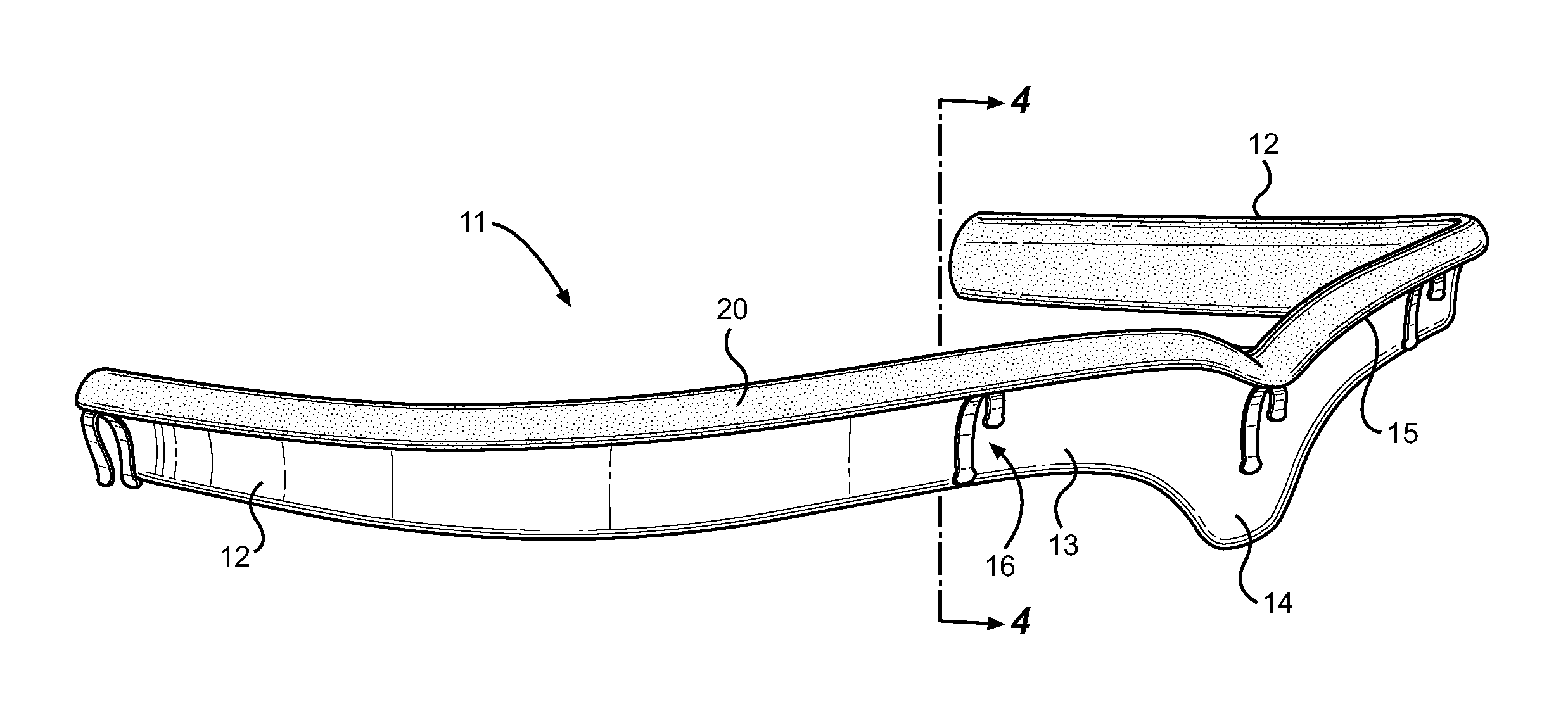
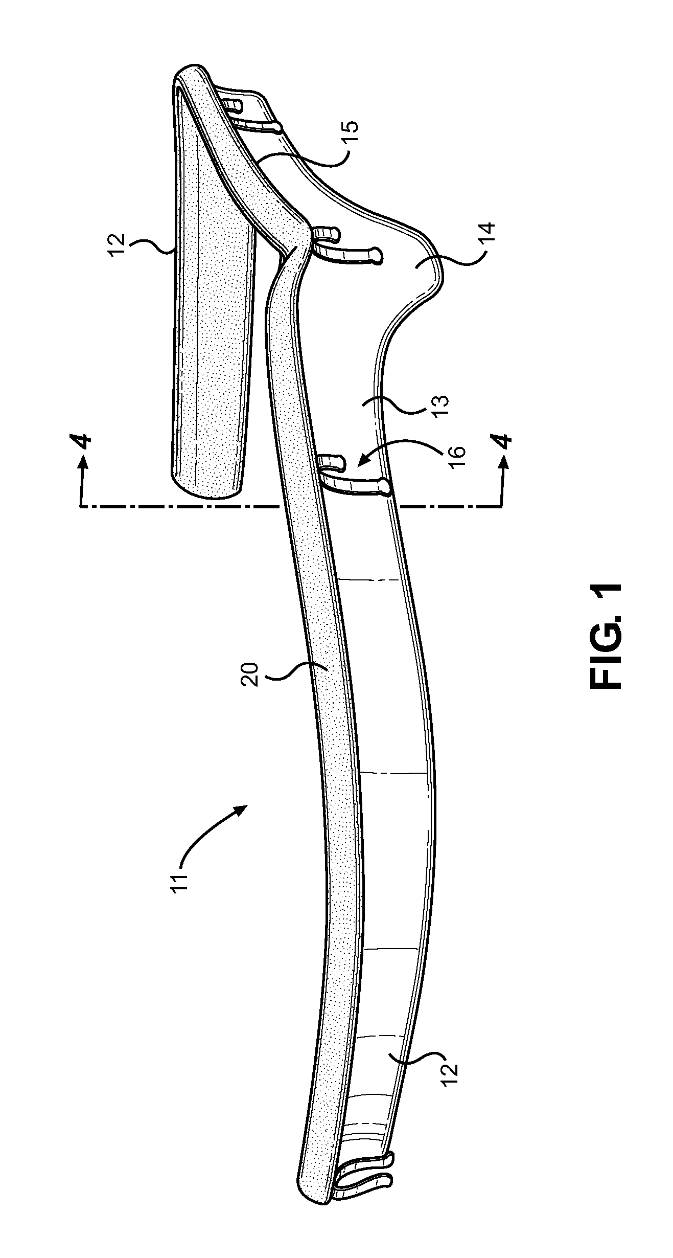
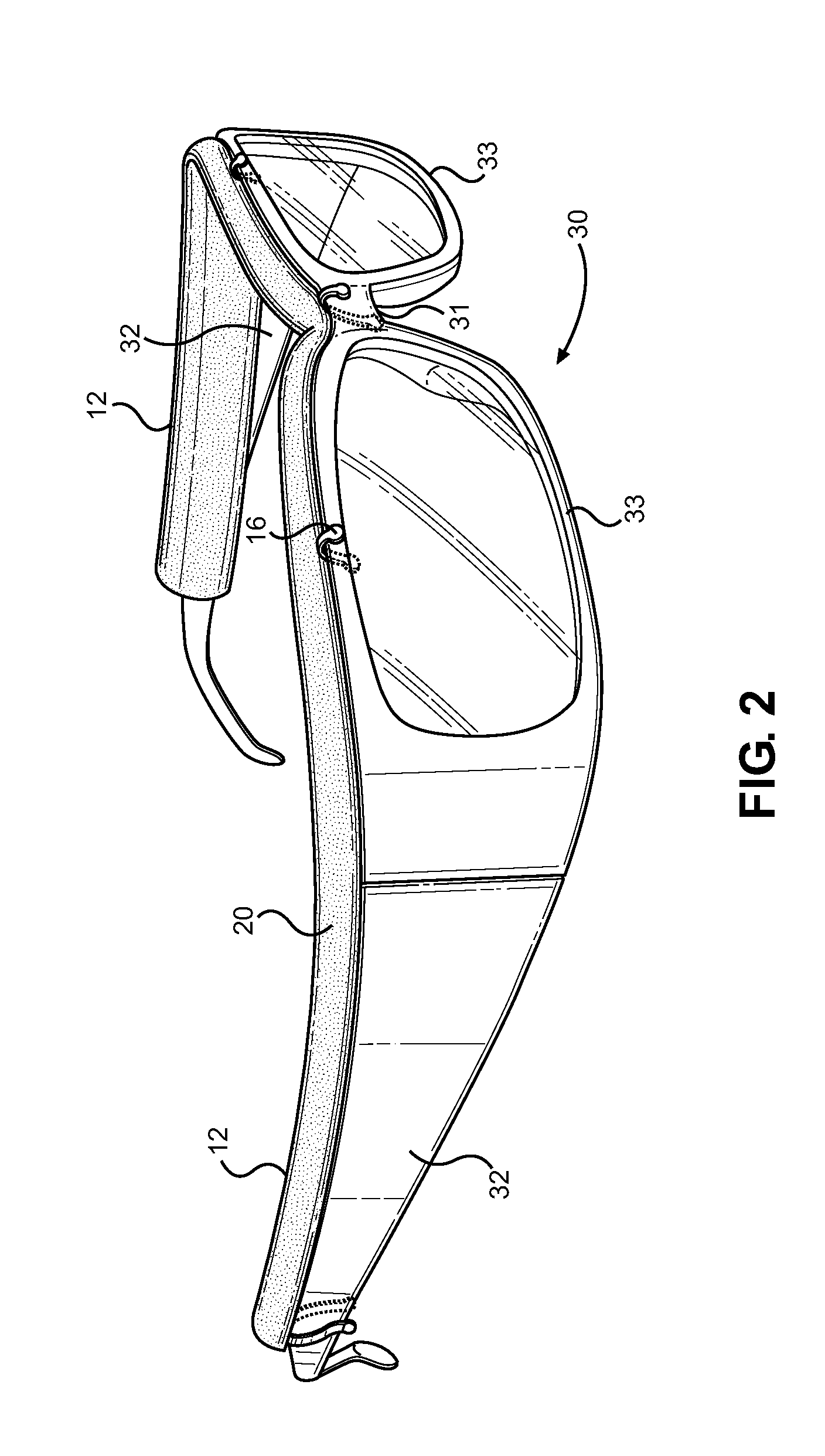
[0032]Referring now to FIG. 1, there is shown a perspective view of the eyewear attachment device of the present invention. The device comprises a substantially U-shaped frame 11 that is adapted to rest against and secure to the upper surfaces of an article of eyewear. Contemplated eyewear include normal reading and prescription glasses, sports and athletic eyewear, as well as more occupational...


PUM


Abstract

A sweat wicking and glare reducing eyeglass attachment is provided that is adapted to secure to the upper surfaces of a pair of eyeglasses or pair of sunglasses. The attachment comprises a U-shaped frame having a frontal portion and a pair of side portions, wherein the cross section of the frame is J-shaped and comprised of an upstanding portion and an upper overhang portion. The overhang portion secures via clips over the top bar, bridge, and upper portions of both eyeglass lenses, while the side portions of the frame secure to the temples of the eyeglass. The frame further comprises a sweat wicking material layer coextensively disposed thereon that is adapted to draw sweat from the user's skin through capillary action and dry swiftly thereafter. Overall, the device acts as a partial visor along the upper portion of eyeglass and a means of absorbing brow sweat from the user.

Description

CROSS REFERENCE TO RELATED APPLICATION[0001]This application claims the benefit of U.S. Provisional Application No. 61 / 739,497 filed on Dec. 19, 2012, entitled “Eyewear Sweatbrow.” The above identified patent application is herein incorporated by reference in its entirety to provide continuity of disclosure.BACKGROUND OF THE INVENTION[0002]1. Field of the Invention[0003]The present invention relates to eyewear connection devices and particularly to devices for preventing unwanted fluid, sunlight, and other particles from entering the user's eyes and field of vision. The device comprises a tube-shaped member having a two layer design that attaches to the upper edge of most any style eyewear. The present invention will be appreciated by those who engage in athletic or active work activity while wearing eyewear.[0004]Various types of eyewear exist in the art for the purposes of improving vision of the user, for protecting the user's eyes during certain activities, and further for provi...

Claims


Application Information

Patent Timeline
IPC IPC(8): G02C11/08G02C7/16
CPCG02C7/16G02C11/08G02C11/00A61F9/02
Inventor SPITZER, ELIZABETH
Owner SPITZER ELIZABETH
Learn More