Automobile Flagpole

Inactive Publication Date: 2014-06-26
TUCKER WILLIAM CHRISTOPHER
View PDF23 Cites 14 Cited by
  • Summary
  • Abstract
  • Description
  • Claims
  • Application Information

AI Technical Summary

Benefits of technology

[0012]The straight portion of the flagpole may extend up far enough for the flag to clear the top of the roof of the automobile; have a generally round or oval cross-section with a raised edge on either side or other shapes allowing for a more ridged cross-section. The straight portion may have a lip located toward the middle of the pole and a lip at the top of the pole to keep the flag from sliding up or down the pole. The portion of the straight section of the pole that the flag wraps around may be thinner than the section of the lower portion of the pole that attaches to the clip.
[0013]In an alternate embodiment, the interior portion of the clip comprises a hinge located just low enough to clear the window frame of the window while in the rolled up position. The portion of the clip above the hinge is the same as the previous embodiment; the lower portion is hinged onto the upper portion allowing flexibility between the upper and lower section and keeping energy transfer between the thrashing flag pole and the suction cup(s) minimal, allowing the suction cup(s) to remain fully seated. Generally the only force exerted on the suction cup(s) is a vertical force allowing the suction cup(s) to maximize its potential and eliminating all horizon

Problems solved by technology

However, such flag poles are intended to operate only when the window is rolled up.
Thus, while the vehicle is moving, the user can not roll down the window or the flag will be lost.
More often than not, the user, other passenger or child simply forgets that a flag is on the window and the flag is lost on the highway after the window is mistakenly rolled down.
Additionally, window mounted flagpoles by nature thrash and blow in the wind at normal driving speeds, thus the flagpole and base move forward and backward

Method used


Image

  • Automobile Flagpole
  • Automobile Flagpole
  • Automobile Flagpole

Examples


Example

[0033]The descriptions and drawings discussed herein are merely to illustrate how to make and use this invention and are not to be interpreted as limiting in scope. Even though the devices and methods have been described with a degree of specificity, it is to be noted that many modifications may be made in the details of the construction and the arrangements of the components without departing from the spirit and scope contained herein. It is to be noted that the devices and methods are not limited to the embodiments set forth herein for purposes of exemplification.

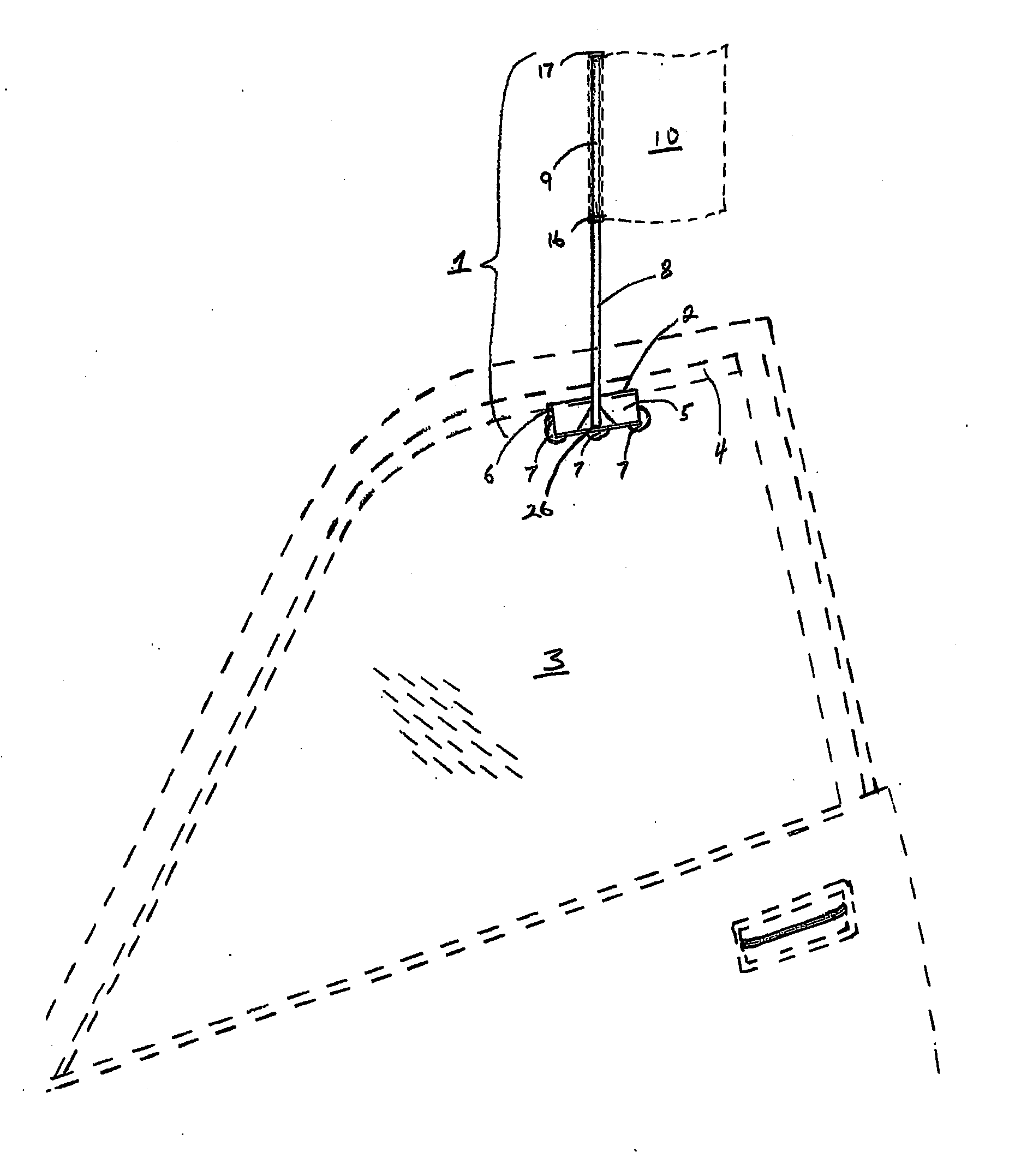
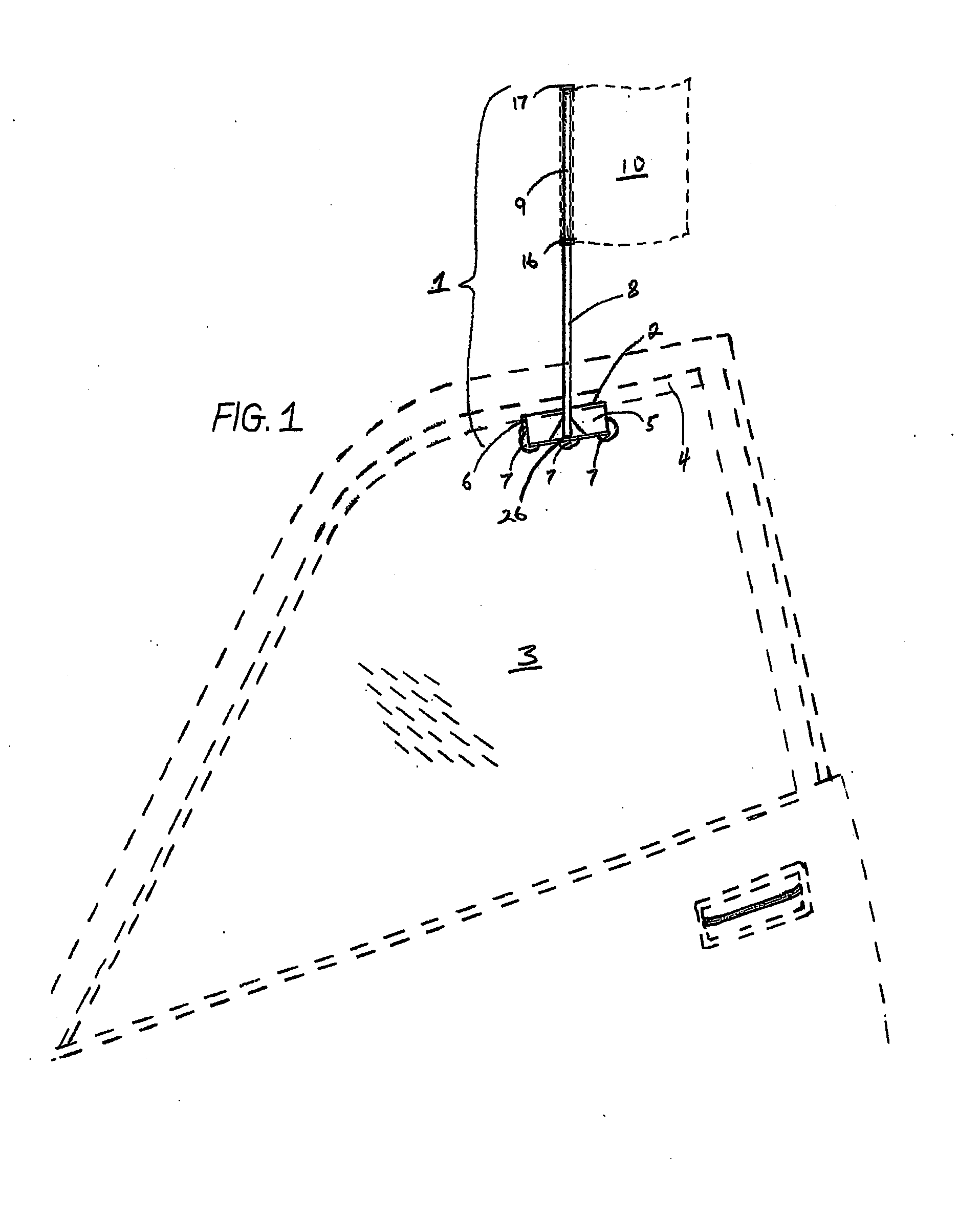
[0034]Referring now in detail to the drawings, wherein like numerals of reference designate like elements throughout the several different views, FIG. 1 shows an automobile flag. The flag pole 1 has a clip portion 2 that is shaped like a “U”, made up of an exterior portion 5 and interior portion 6 and fits over the top of the side window 3 of an automobile in which the flagpole 1 is held into place when the clip 2 is plac...


PUM


Abstract

An automobile flagpole comprising a clip portion, where the clip portion is “U” shaped in order to fit over an automobile window and to be held in place when the window is in the up position; a straight portion that extends upwards from the exterior portion of the clip, with an attached flag; the interior portion of the clip extends downward and one or more suction cups are attached in such a way to limit forces applied upon the flagpole from reaching the suction cup(s); thus allowing the flagpole to be operated on the automobile with the window either up or down.

Description

CROSS-REFERENCE TO RELATED APPLICATIONS[0001]This application claims the benefit of U.S. Provisional Patent Application 61 / 742,226, which was filed on Aug. 6, 2012, the entire disclosure of which is hereby incorporated by reference.STATEMENT REGARDING FEDERALLY SPONSORED RESEARCH OR DEVELOPMENT[0002]Not ApplicableREFERENCE TO SEQUENCE LISTINGS, A TABLE, COMPUTER PROGRAM LISTING COMPACT DISC APPENDIX[0003]Not ApplicableBACKGROUND OF THE INVENTION[0004]1. Field of the Invention[0005]This invention generally relates to automobile flags. Particularly to window mounted automobile flags and more particularly to window mounted automobile flags that comprise a clip that fits over the top of an automobile's side window and is held in place by the window and window frame when the window is rolled up. Specifically, this invention comprises a flag mounting system in which the window can be rolled down or partially rolled down and the flag mounting system will stay in place and will not blow off...

Claims


Application Information

Patent Timeline
IPC IPC(8): G09F17/00
CPCG09F17/00G09F2017/0075G09F2017/0066
Inventor TUCKER, WILLIAM CHRISTOPHER
Owner TUCKER WILLIAM CHRISTOPHER
Why Eureka
Try Eureka