

Multicore fiber for communication
a fiber optic and multi-core technology, applied in the field of multi-core fiber for communication, can solve the problems of affecting the performance of the fiber optics, the distance between the outer peripheral surface, and the loss of microbends,
- Summary
- Abstract
- Description
- Claims
- Application Information
AI Technical Summary
Benefits of technology
Problems solved by technology
Method used
Image

Examples
first embodiment
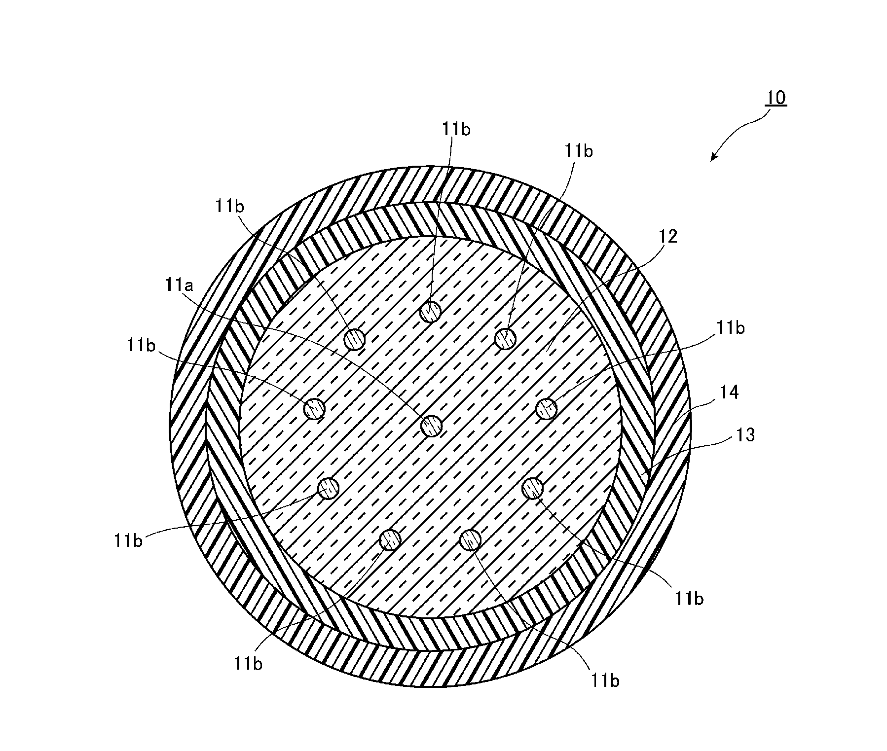
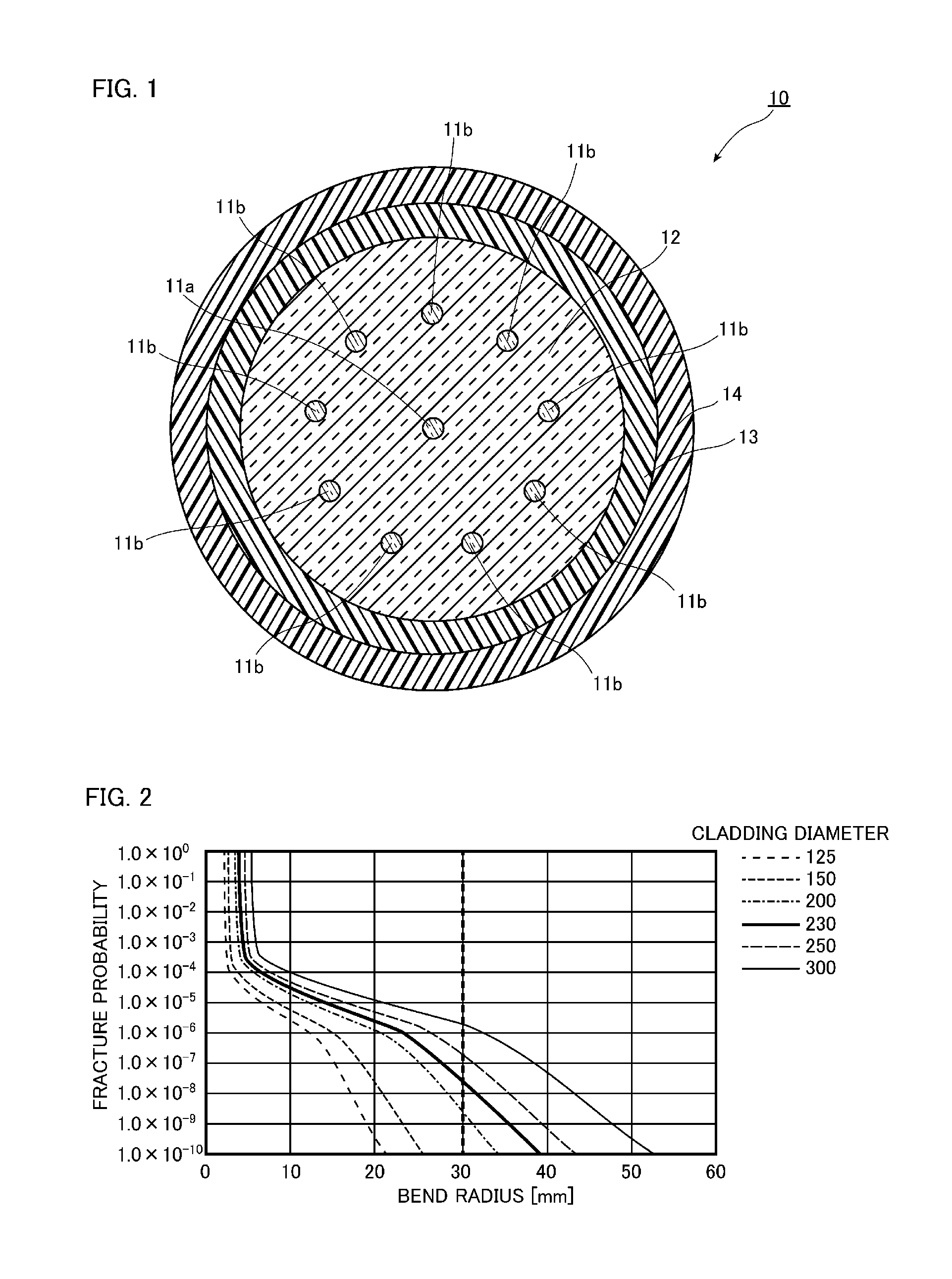
[0039]FIG. 1 is a view illustrating a structure of a vertical cross section of a multicore fiber in a longitudinal direction according to a first embodiment of the present invention. As illustrated in FIG. 1, a multicore fiber 10 according to the present embodiment has a clad 12, a core 11a which is arranged in the center in a cross section of the clad 12, nine cores 11b which are arranged at equal intervals surrounding the core 11a, an inner protective layer 13 which covers an outer peripheral surface of the clad 12 and an outer protective layer 14 which covers an outer peripheral surface of the inner protective layer 13. That is, in the multicore fiber 10 according to the present embodiment, a plurality of cores 11a and 11b is provided in a 1-9 arrangement.
[0040]This multicore fiber 10 is an optical fiber which allows propagation of an optical signal, and a mode field diameter of light propagating in the cores 11a and 11b is preferably 9 μm to 13 μm. The mode field diameter is 9 μ...
second embodiment
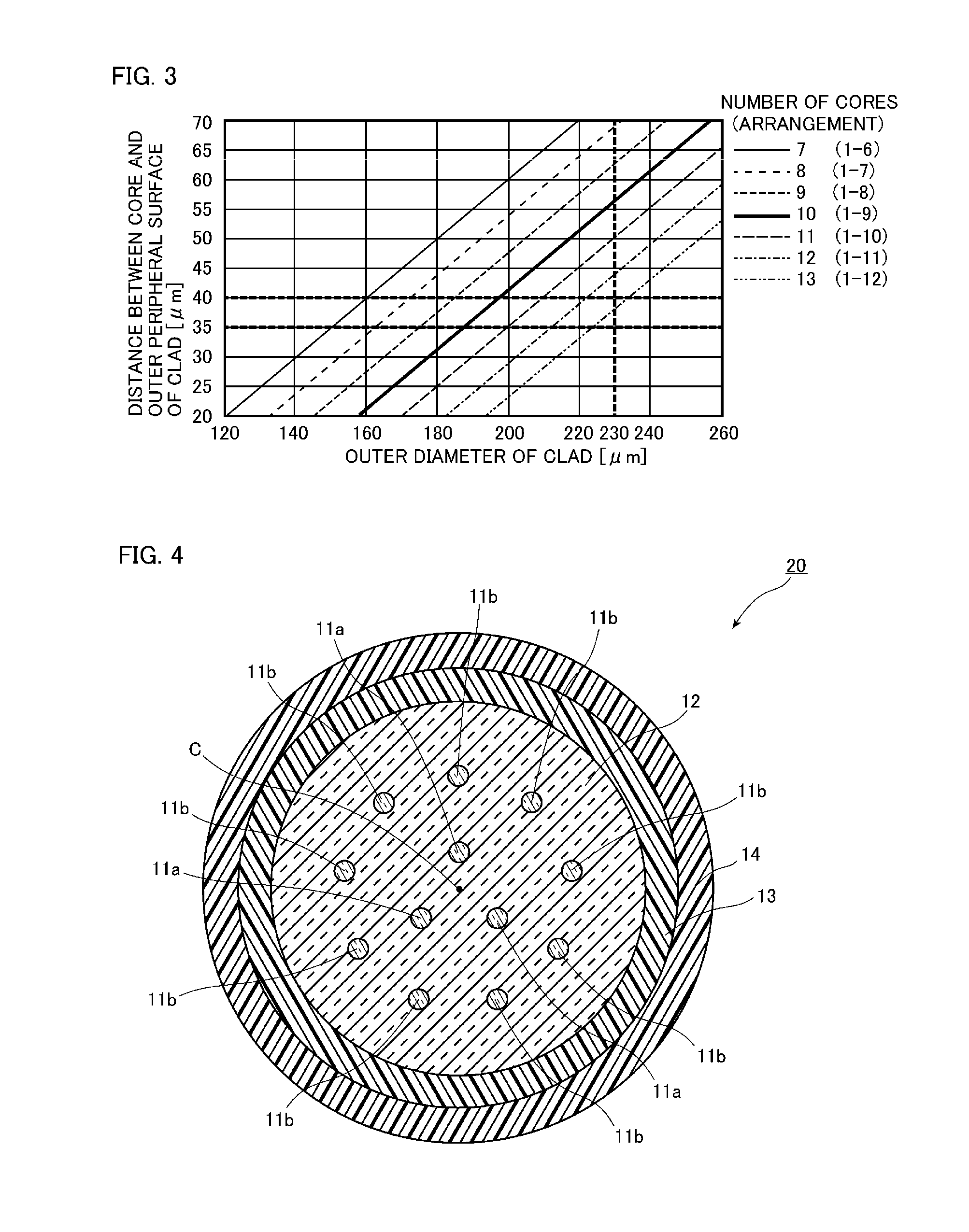
[0062]Next, referring to FIG. 4, a second embodiment of the present invention will be described in detail. In addition, components that are identical or similar to those in the first embodiment will be denoted by the same reference numerals as those used in the first embodiment unless particularly described, and will not be described.
[0063]FIG. 4 is a view illustrating a structure of a vertical cross section of a multicore fiber in a longitudinal direction according to the second embodiment of the present invention. As illustrated in FIG. 4, a multicore fiber 20 according to the present embodiment differs from a multicore fiber 10 according to the first embodiment in an arrangement of cores 11a and 11b. More specifically, three cores 11a are arranged at equal intervals surrounding a center C in a cross section of a clad 12, and nine cores 11b are arranged around the center C of the clad 12 surrounding these three cores 11a. That is, in the multicore fiber 20 according to the present...
third embodiment
[0069]Next, referring to FIG. 5, a third embodiment of the present invention will be described in detail. In addition, components that are identical or similar to those in the first embodiment will be denoted by the same reference numerals as those used in the first embodiment unless particularly described, and will not be described.
[0070]FIG. 5 is a view illustrating a structure of a vertical cross section of a multicore fiber in a longitudinal direction according to a third embodiment of the present invention. As illustrated in FIG. 5, a multicore fiber 30 according to the present embodiment differs from a multicore fiber 10 according to the first embodiment in a core 11a arranged in the center, a plurality of cores 11b and, in addition, a plurality of cores 11c arranged on an outermost periphery side. More specifically, the core 11a is arranged in the center in the cross section of a clad 12, the outermost periphery side six cores 11c are arranged at equal intervals surrounding t...
PUM
 Abstract
Description
Claims
Application Information