Method and system for position orientation correction in navigation

Active Publication Date: 2014-07-03
STRYKER EURO OPERATIONS HLDG LLC
View PDF2 Cites 107 Cited by
  • Summary
  • Abstract
  • Description
  • Claims
  • Application Information

AI Technical Summary

Benefits of technology

[0003]In one embodiment, a method performed in a medical navigation system includes driving a transmitter at a first frequency and at least a second frequency to generate a first and a least a second electromagnetic field, wherein the first and second frequencies are sufficiently low such that the first and second electromagnetic fields are frequency independent; receiving a first and at least a second distorted field corresponding to the first and second electromagnetic fields, respectively, with each of at least two electromagnetic (EM) sensors attached to a surgical device; generating a first and at least a second signal in response to receiving the first and second distorted fields, respectively, using each of the at least two EM sensors; and determining a distortion in the first and at least the second signals based at least on a distance between the at least two EM sensors and a difference between the first and second signals generated by each of the at least two EM sensors.
[0004]In another embodiment, a medical navigation system includes a transmitter configured to emit electromagnetic (EM) fields in response to current at one or more f

Problems solved by technology

Because some sensors operate based on electromagnetism, one issue that can arise with navigation sensors suitable for acquiring position and orientation information in this manner is the position and orientation errors that may be caused by the presence of metallic objects in the field of navigation.
Unfortunately, these errors can result in incorrect positioning of a medical device during

Method used


Image

  • Method and system for position orientation correction in navigation
  • Method and system for position orientation correction in navigation
  • Method and system for position orientation correction in navigation

Examples


Embodiment Construction

[0014]One or more specific embodiments of the present disclosure will be described below. In an effort to provide a concise description of these embodiments, all features of an actual implementation may not be described in the specification. It should be appreciated that in the development of any such actual implementation, as in any engineering or design project, numerous implementation-specific decisions must be made to achieve the developers' specific goals, such as compliance with system-related and business-related constraints, which may vary from one implementation to another. Moreover, it should be appreciated that such a development effort might be complex and time consuming, but would nevertheless be a routine undertaking of design, fabrication, and manufacture for those of ordinary skill having the benefit of this disclosure.

[0015]When introducing elements of various embodiments of the present invention, the articles “a,”“an,”“the,” and “said” are intended to mean that the...


PUM


Abstract

A method performed in a medical navigation system includes driving a transmitter at a first frequency and a second frequency to generate first and second electromagnetic fields, wherein the first and second frequencies are sufficiently low such that the first and second electromagnetic fields are frequency independent; receiving first and second distorted fields corresponding to the first and second electromagnetic fields, respectively, with each of at least two electromagnetic (EM) sensors attached to a surgical device; generating first and second signals in response to receiving the first and second distorted fields, respectively, using each of the at least two EM sensors; and determining a distortion in the first and second signals based at least on a distance between the at least two EM sensors and a difference between the first and second signals generated by each of the at least two EM sensors.

Description

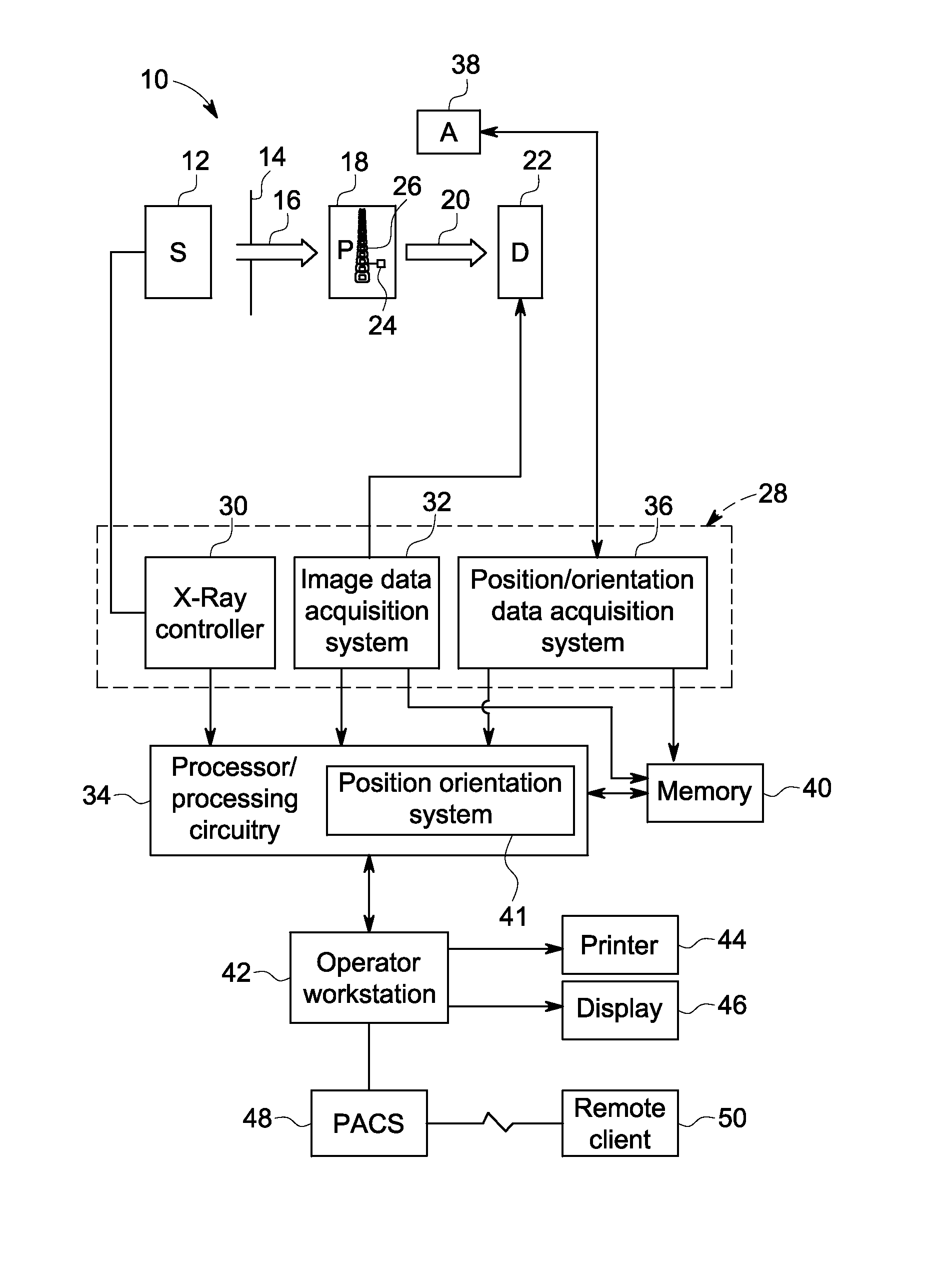
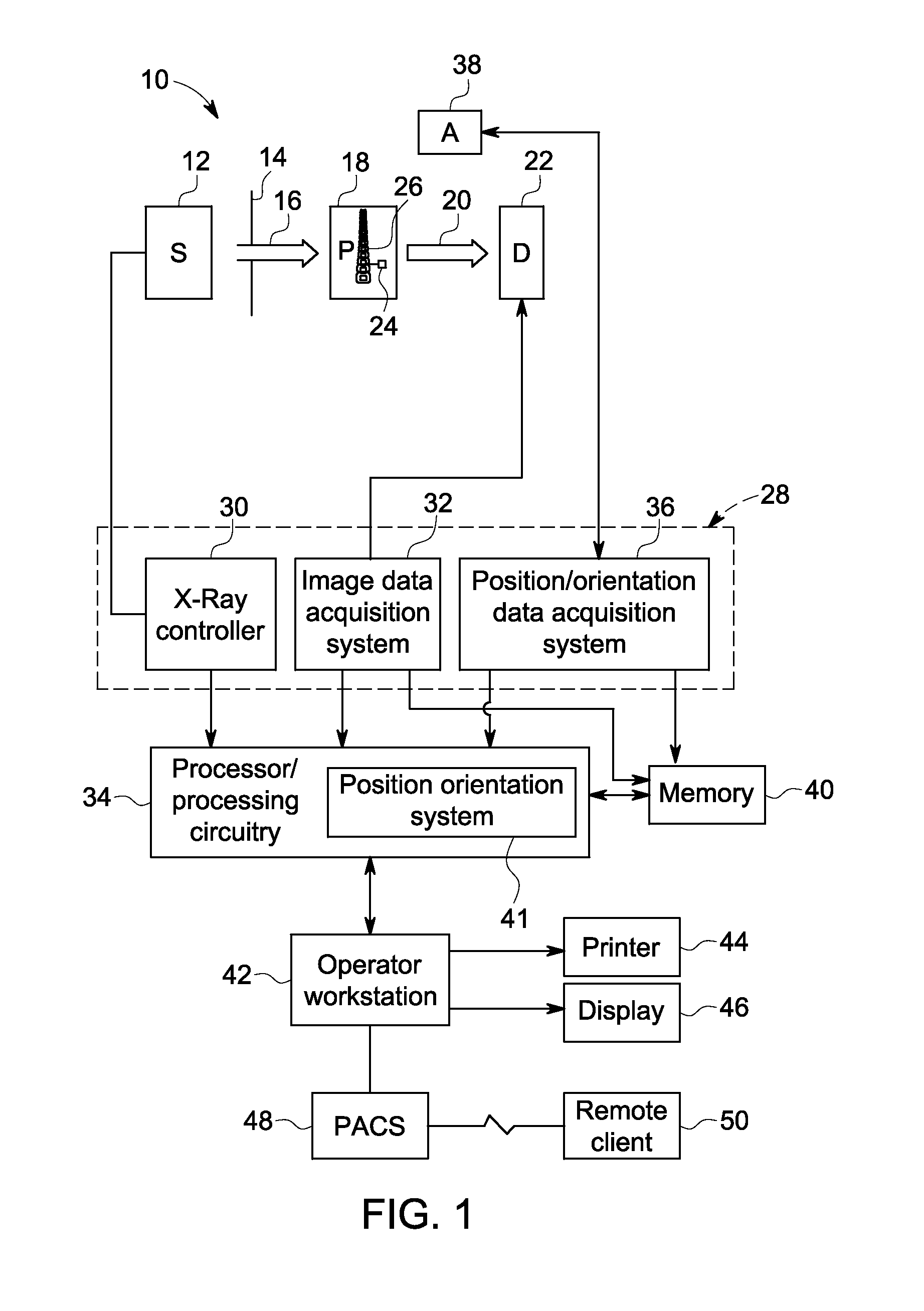
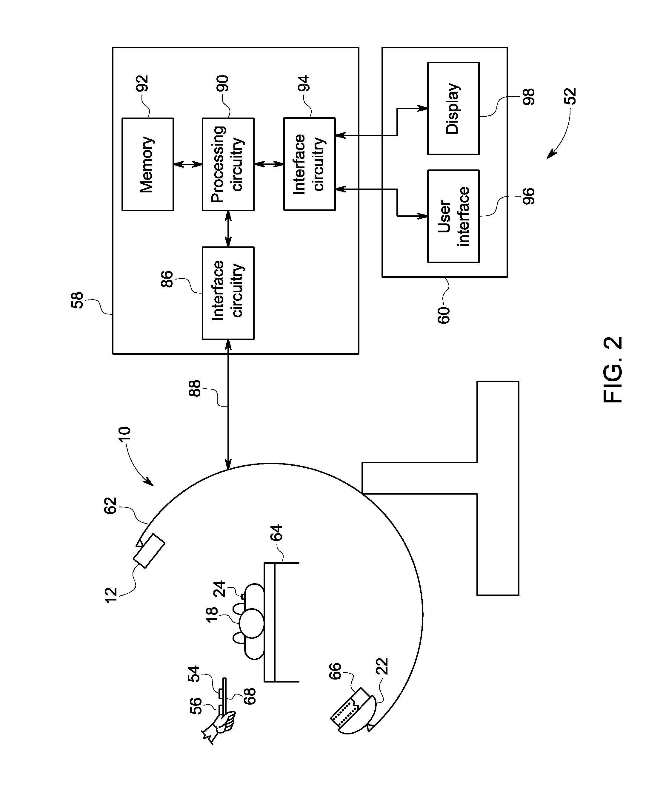
BACKGROUND[0001]In various medical contexts it may be desirable to acquire position and / or orientation information for a medical instrument, implant or device that is navigated or positioned (externally or internally) relative to a patient. For example, in surgical and / or interventional contexts, it may be useful to acquire position and / or orientation information for a medical device, or a portion of a medical device, when the device or relevant portion is otherwise out of view, such as within a patient's body. Likewise, in certain procedures where an imaging technique is used to observe all or part of the position and orientation information, it may be useful to have position and orientation information derived from the tracked device itself that can be related to the image data also being acquired.[0002]Because some sensors operate based on electromagnetism, one issue that can arise with navigation sensors suitable for acquiring position and orientation information in this manner ...

Claims


Application Information

Patent Timeline
IPC IPC(8): A61B5/06A61B6/12A61B17/16A61M1/00A61B17/28A61B17/32A61B17/86A61B17/84A61B17/06A61B17/34A61M25/09A61F2/82A61F2/01A61B1/313A61N1/04A61B6/00A61B6/03A61B5/055A61B5/00
CPCA61B5/062A61N1/04A61B17/06A61B17/16A61B17/28A61B17/32A61B17/34A61B17/846A61B17/86A61B5/055A61B5/686A61B5/72A61B5/7425A61B6/032A61B6/12A61B6/467A61B6/5247A61B6/54A61F2/01A61F2/82A61M1/00A61M25/09A61B1/313A61B6/4441A61B6/463A61B6/487A61B17/00234A61B34/20A61B2034/2051A61B2090/376
Inventor YAROSHENKO, ANDRIYOBI, AGHOGHO
Owner STRYKER EURO OPERATIONS HLDG LLC
Why Eureka
Try Eureka