Work vehicle

Active Publication Date: 2014-07-03
HITACHI CONSTR MASCH CO LTD
View PDF0 Cites 7 Cited by
  • Summary
  • Abstract
  • Description
  • Claims
  • Application Information

AI Technical Summary

Benefits of technology

[0013]According to the present invention, it is possible to suppress the worsening of ride comfo

Problems solved by technology

When the torque converter-equipped vehicle travels, the consumed power of the hydraulic pump (power of the load exerted by the h

Method used


Image

  • Work vehicle
  • Work vehicle
  • Work vehicle

Examples


Example

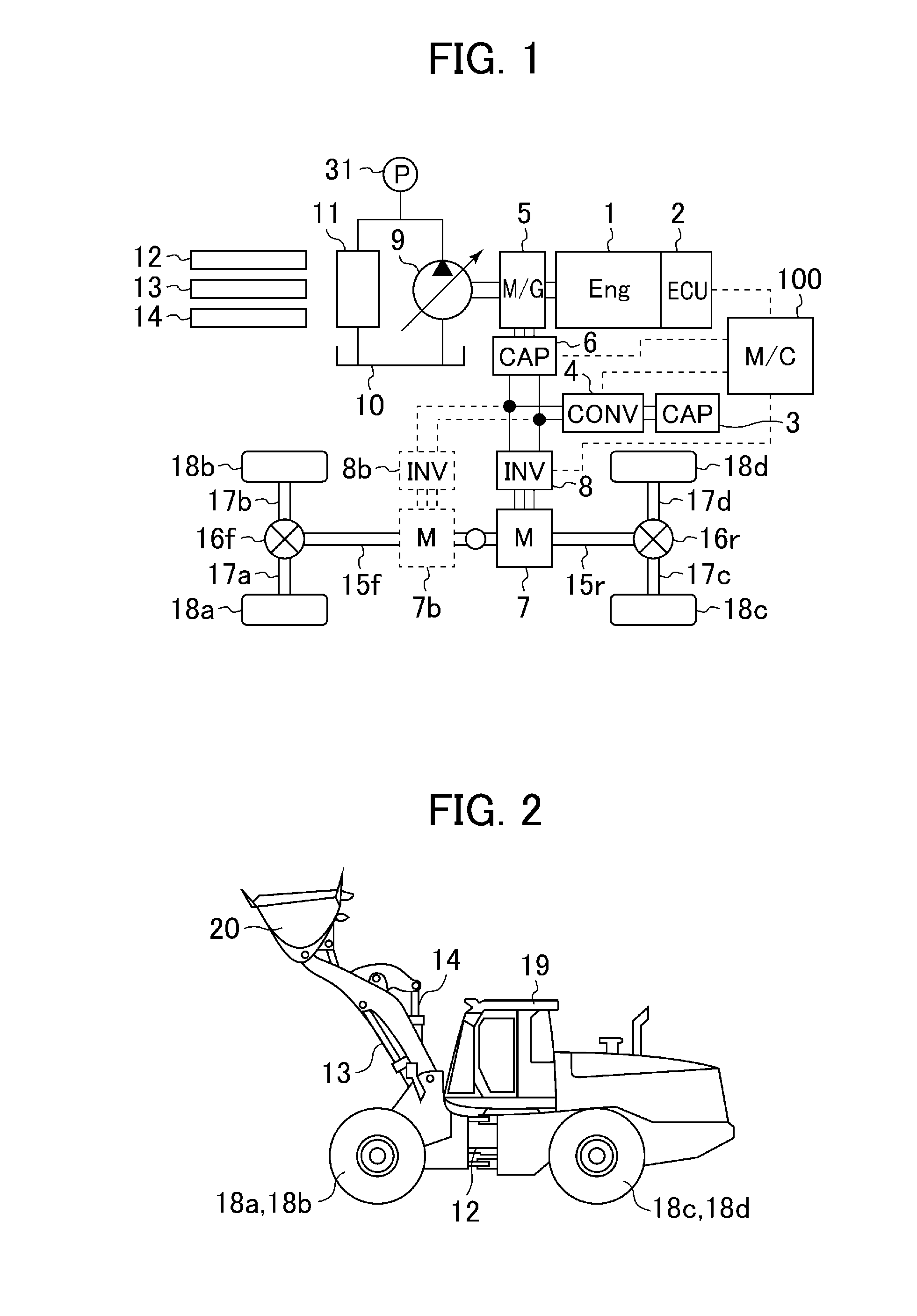
[0024]Some embodiments of the present invention are explained below with reference to the accompanying drawings. FIG. 1 is a block diagram of a work vehicle as one embodiment of the invention.

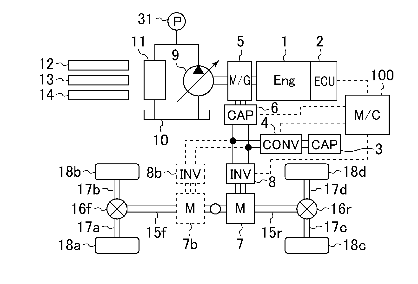
[0025]The work vehicle shown in FIG. 1 includes a main controller (main control unit) 100, an engine 1, an engine controller (engine control unit) 2 that controls the engine 1, a capacitor 3 acting as an electrical storage device, a converter 4 that controls charging and discharging of the capacitor 3, a motor generator 5 connected mechanically to the engine 1 and connected electrically to the capacitor 3, a generator inverter 6 that drives the motor generator 5, traveling motors 7 and 7b that are connected electrically to the motor generator 5 and capacitor 3 and run on electrical power supplied therefrom, and traveling inverters 8 and 8b that control driving of the traveling motors 7 and 7b respectively.

[0026]Also, the work vehicle of this embodiment includes a main pump (hydraulic pump) 9 co...


PUM


Abstract

When the total value of demanded hydraulic power and demanded traveling power is larger than the sum of the engine power that can be output by an engine (1) and of the discharge power that can be discharged by an electrical storage device (3), the actual power of a hydraulic pump (9) is increased from the value at the time of demand toward the demanded hydraulic power under the constraint of a predetermined limit. While the power of the hydraulic pump is being subjected to the predetermined limit, the actual power of the traveling motor is decreased from the value at the time of demand by a value smaller than the magnitude of the predetermined limit. This prevents worsening of ride comfort attributable to the distribution of power between the hydraulic pump and the traveling motor.

Description

TECHNICAL FIELD[0001]The present invention relates to a work vehicle. More particularly, the invention relates to the distribution of power during compound motion.BACKGROUND ART[0002]Among conventional work vehicles, there exists a wheel loader equipped with an engine, a hydraulic pump coupled mechanically to the output shaft of the engine, hydraulic actuators operated with a fluid supplied from the hydraulic pump, and an automatic transmission operating on a torque converter coupled mechanically to the output shaft of the engine (the wheel loader will be called the torque converter-equipped vehicle hereunder). The torque converter-equipped vehicle travels by having the engine power transmitted to its wheels through the automatic transmission, propeller shafts, differential gears, and drive shafts. Also, the torque converter-equipped vehicle has its front mechanism operated by extending and contracting the hydraulic actuators to move a bucket to excavate, load, and haul gravel or th...

Claims


Application Information

Patent Timeline
IPC IPC(8): E02F9/22E02F9/20B60K6/46B60W20/00B60W10/08B60L50/15B60L50/16
CPCE02F9/2075E02F9/2095E02F9/2235E02F9/2296B60W20/1088B60K6/12B60K6/46B60L11/005B60L11/1803B60L15/2009B60W10/06B60W10/08B60W10/24B60W10/26B60W20/00B60W30/1888B60L2200/40B60L2210/10B60L2220/42B60L2240/421B60L2240/423B60L2240/441B60L2260/28B60W2510/0666B60W2510/09B60W2510/305Y02T10/7005Y02T10/6286Y02T10/7022Y02T10/7216Y02T10/648B60W2300/17Y02T10/6282Y02T10/6217Y02T10/6208E02F9/0841E02F9/2079E02F9/2246Y10S903/93B60W20/19B60L50/40B60L50/51Y02T10/62Y02T10/64Y02T10/70Y02T10/72B60K6/52B60L7/14B60L2210/40B60L2240/12B60L2240/443B60L2250/24B60W10/30B60W30/1886B60L50/16B60L50/61Y02T10/7072
Inventor MORIKI, HIDEKAZUKANEKO, SATORUIKIMI, TAKASHIITO, NORITAKA
Owner HITACHI CONSTR MASCH CO LTD
Why Eureka
Try Eureka