Knee side face restraint airbag device

a knee side face and airbag technology, which is applied in the direction of pedestrian/occupant safety arrangement, vehicular safety arrangment, vehicle components, etc., to achieve the effect of improving the performance facilitating the improvement of knee side face restraint, and simplifying the design of door trims

Active Publication Date: 2014-07-17
TOYOTA JIDOSHA KK
View PDF10 Cites 8 Cited by
  • Summary
  • Abstract
  • Description
  • Claims
  • Application Information

AI Technical Summary

Benefits of technology

[0044]The knee side face restraint airbag device of the third aspect has the excellent advantageous effects of rendering reinforcement measures to receive deployment reaction force of the knee side face restraint airbag unnecessary, and of enabling the knee side face restraint airbag to be quickly inflated and deployed between the knee side face and a vehicle cabin inside face of a vehicle side portion since the knee side face restraint airbag deploys with stable posture.
[0045]The knee side face restraint airbag device of the fourth aspect has the excellent advantageous effect of enabling the design of the door trim to be simplified.
[0046]The knee side face restraint airbag device of the fifth aspect has the excellent advantageous effect of enabling knee side face restraining performance to be improved.
[0047]The knee side face restraint airbag device of the sixth aspect has the excellent advantageous effects of enabling the knee side face of the seated occupant to be restrained in the event of a frontal collision (in particular in the event of a small overlap collision or an oblique collision) in a wider range of vehicle types, and of enabling greater commonality of components to be achieved.
[0048]The knee side face restraint airbag device of the seventh aspect has the excellent advantageous effect of enabling the design of the door trim to be simplified.
[0049]The knee side face restraint airbag device of the eighth aspect has the excellent advantageous effect of being able to reduce or prevent twisting of the ankle of an occupant in the event of a frontal collision (in particular in the event that a small overlap collision or an oblique collision was happened at the seated occupant side).

Problems solved by technology

However, in JP-A No. 2003-327073 the supports are formed to the door trim as projection portions, and sideways motion of the leg is not restrained until the thigh, shin or foot come into contact with the door trim.

Method used


Image

  • Knee side face restraint airbag device
  • Knee side face restraint airbag device
  • Knee side face restraint airbag device

Examples


first exemplary embodiment

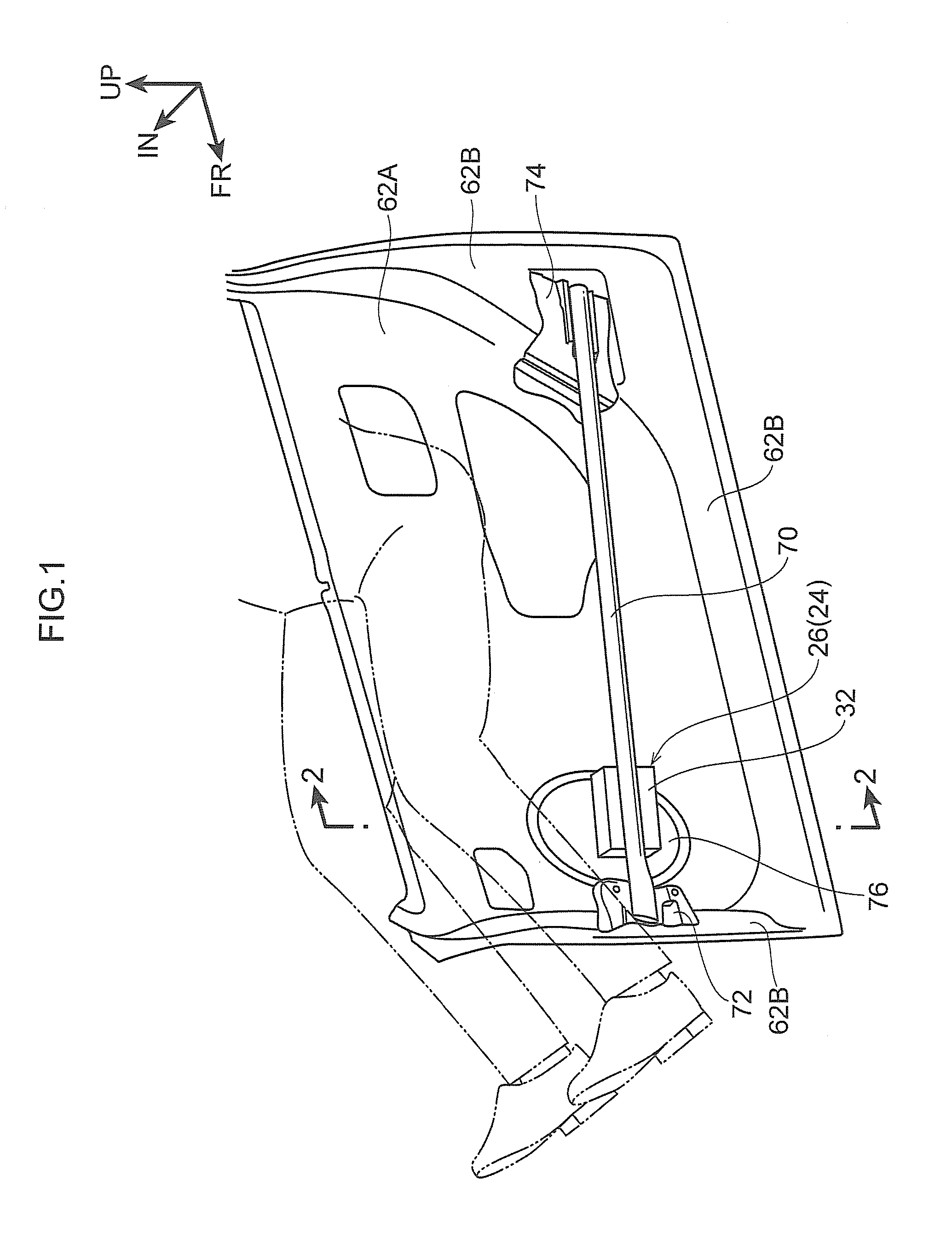
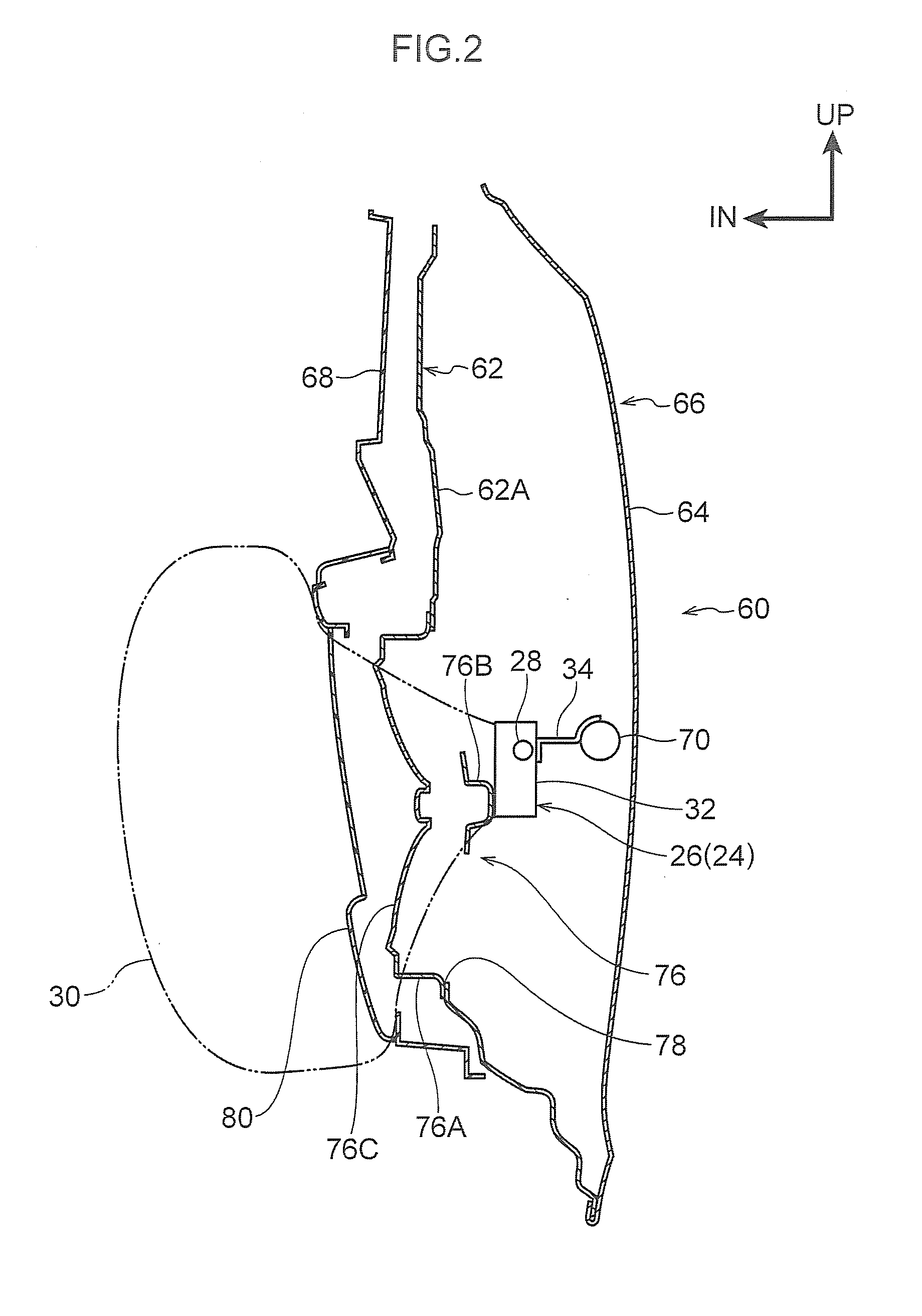
[0075]A knee side face restraint airbag device of a first exemplary embodiment of the present invention is described below with reference to FIG. 1 to FIG. 5. Note that in each of the drawings the vehicle front side is indicated by an arrow FR and the vehicle upper side is indicated by an arrow UP as appropriate. The vehicle width direction inside is indicated by an arrow IN. The vehicle illustrated in these drawings is a left-hand drive vehicle.

[0076]As illustrated in FIG. 5, a driver's seat 10 and a passenger's seat 12 are disposed alongside one another in the vehicle width direction in a cabin C. The driver's seat 10 includes: a seat cushion 14 upon which an occupant sits; a seatback 16 that is reclinably supported at a rear end portion of the seat cushion 14 and that supports the back of the seated occupant; and a headrest 18 (see FIG. 3) that is disposed at an upper end portion of the seatback 16 so as to be moving up and down, and that supports the head of the seated occupant....

second exemplary embodiment

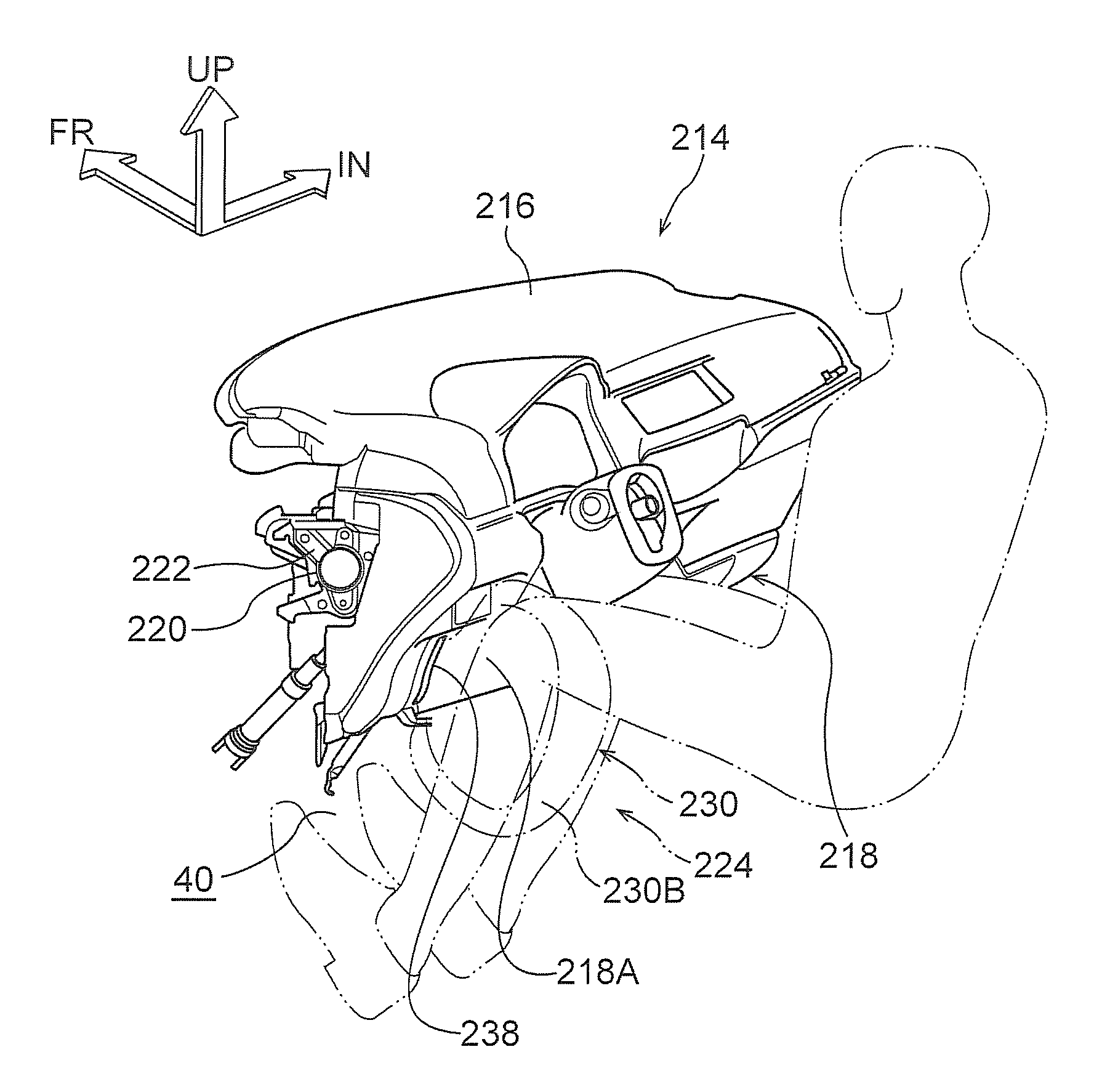
[0095]Explanation follows regarding a knee side face restraint airbag of a second exemplary embodiment of the present invention, with reference to FIG. 6 to FIG. 12. Note that in each of the drawings an arrow FR indicates the vehicle front side and an arrow UP indicates the vehicle upper side where appropriate. An arrow IN indicates the vehicle width direction inside. Note that the vehicle illustrated in these drawings is a left-hand drive vehicle.

[0096]As illustrated in FIG. 6 to FIG. 8, a resin instrument panel 214 is disposed to the vehicle front side of a driver's seat 210 and a passenger's seat 212 (see FIG. 7). The instrument panel 214 is configured by: an instrument panel upper member 216 that configures an upper portion; and an instrument panel lower member 218 that is disposed at the vehicle lower side of the instrument panel upper member 216 and integrated together with the instrument panel upper member 216 by means of engagement claws. Instrument panel reinforcement 220 t...

third exemplary embodiment

[0115]A knee side face restraint airbag device of a third exemplary embodiment of the present invention is described below with reference to FIG. 13 to FIG. 17. Note that an arrow FR indicates the vehicle front side and an arrow UP indicates the vehicle upper side in each of the drawings as appropriate. An arrow IN indicates the vehicle width direction inside. The vehicle illustrated in the drawings is a left-hand drive vehicle.

[0116]As illustrated in FIG. 17, outsides of a driver's seat 310 and a passenger's seat 312 are configured similarly to those in the first exemplary embodiment.

[0117]As illustrated in FIG. 13 and FIG. 14, a seat cushion 314 is provided with a seat cushion frame 320 that is assembled into a rectangular frame shape in plan view. The seat cushion frame 320 is configured by: a pair of left and right seat side frames 321 that are respectively disposed with length direction along the vehicle front-rear direction and are separated each other in a vehicle width direc...


PUM


Abstract

A knee side face restraint airbag device comprising an inflator that generates gas upon actuation; and a knee side face restraint airbag that is disposed in a folded state at an outside in a vehicle width direction at an inside of a vehicle interior member, that inflates and deploys towards a vehicle cabin inside upon being supplied with gas generated from the inflator, and that restrains an outer lateral-side of a knee of a seated occupant.

Description

CROSS-REFERENCE TO RELATED APPLICATION[0001]This application claims priorities under 35 USC 119 from Japanese Patent Applications No. 2013-005656 filed on Jan. 16, 2013, No. 2013-011528 filed on Jan. 24, 2013, and No. 2013-011529 filed on Jan. 24, 2013, the disclosures of which are incorporated by reference herein.BACKGROUND[0002]1. Technical Field[0003]The present invention relates to a knee side face restraint airbag device.[0004]2. Related Art[0005]Japanese Patent Application Laid-Open (JP-A) No. 2003-327073 discloses technology relating to a vehicle occupant protection device that aims to precisely determine the collision type in the event of a vehicle collision and restrain an occupant in an optimum state according to the collision type. In this technology, a thigh support, shin support and foot support that act as supports to restrain sideways motion of an occupant during an oblique collision, are formed as projection portions to a door trim so as to suppress in-out rotation o...

Claims


Application Information

Patent Timeline
Patent Type & Authority Applications(United States)
IPC IPC(8): B60R21/206B60R21/231
CPCB60R21/23138B60R21/206B60R21/205B60R21/207B60R21/21B60R2021/23169
Inventor MURAJI, MASAOYOSHIKAWA, MASAYUKITAGUCHI, KOSUKEOZAWA, KOHEI
Owner TOYOTA JIDOSHA KK
Why Eureka
Try Eureka