Display device

a display device and display technology, applied in the field of display devices, can solve problems such as display quality deterioration, rainbow-colored glare, and adverse iridescen

Inactive Publication Date: 2014-07-17
JAPAN DISPLAY INC
View PDF0 Cites 18 Cited by
  • Summary
  • Abstract
  • Description
  • Claims
  • Application Information

AI Technical Summary

Benefits of technology

[0010]There is provided a display device including a reflective image display unit having a sheet-like anisotropic scattering member, wherein the sheet-like anisotropic scattering member has a surface in which both a low refractive index area and a high refractive index area exist, the sheet-like anisotropic scattering member is disposed so that a light enters from a first surface of the sheet-like anisotropic scattering member and exits as scattered light from a second surface of the sheet-like anisotropic scattering member, when an extent of refractive index difference at a boundary or vicinity thereof between the low refractive index area and the high refractive index area is relatively large in the first surface and relatively small in the second surface, and the display device satisfies mathematical formulae,

Problems solved by technology

In a display device employing such an anisotropic scattering member, an adverse iridescence such as rainbow-colored glare may occur because of optical interference due to a microstructure of the anisotropic scattering member.
Thus, a display quality may be deteriorated.

Method used


Image

  • Display device
  • Display device
  • Display device

Examples


first embodiment

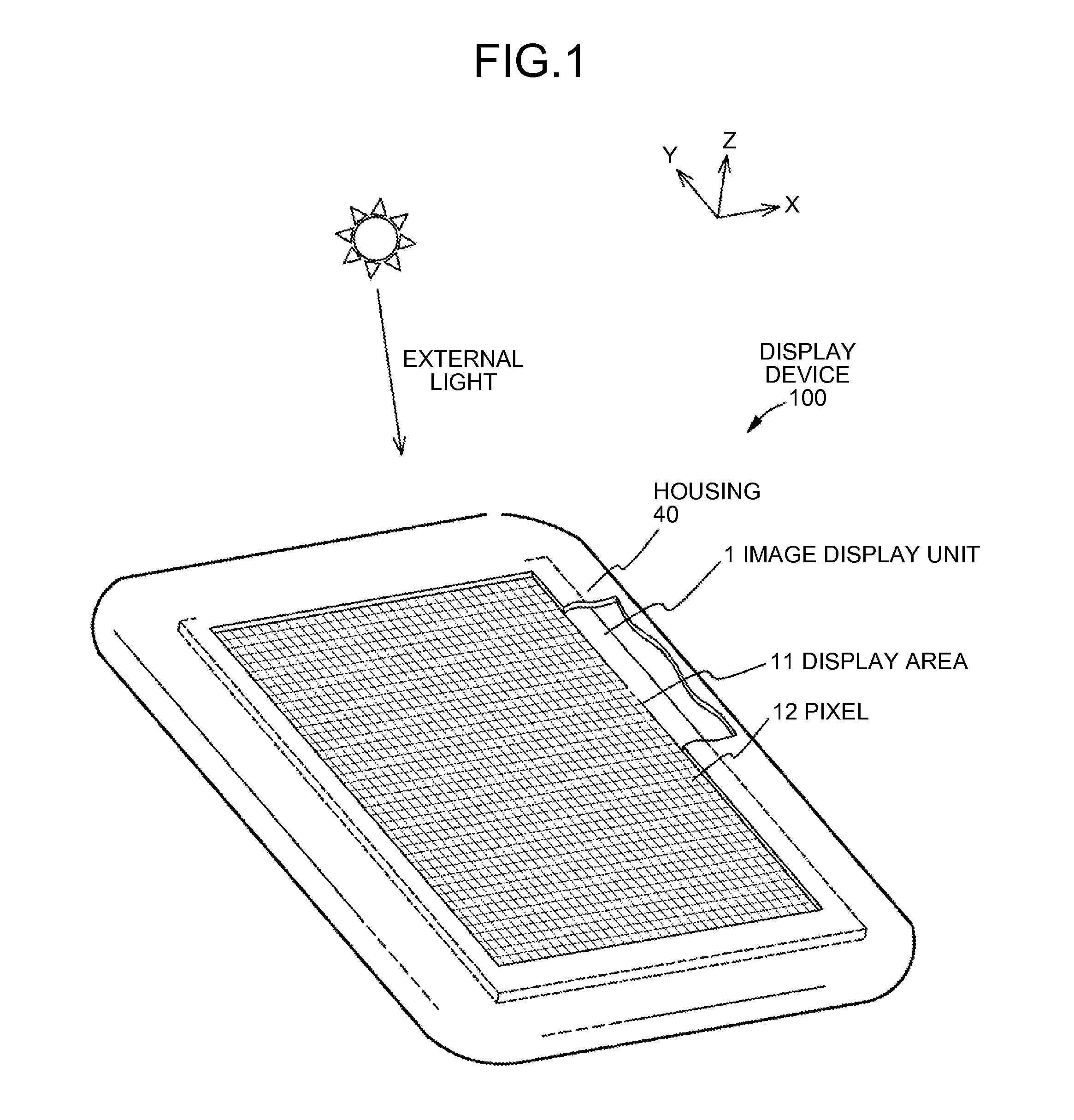
[0060]A first embodiment relates to a display device according to the present disclosure. FIG. 1 is a schematic perspective view of the display device according to the first embodiment.

[0061]As illustrated in FIG. 1, a display device 100 includes a reflective image display unit 1 having a display area 11 in which pixels 12 are arrayed. The image display unit 1 is formed of a reflective liquid crystal display panel and is incorporated in a housing 40. The image display unit 1 is driven by a drive circuit, which is not illustrated, for example. In FIG. 1, a part of the housing 40 is cut out. External light, such as sunlight, enters the display area 11. For convenience of explanation, an assumption is made that the display area 11 is parallel to the X-Y plane and that the side from which an image is observed is positioned in the +Z-direction.

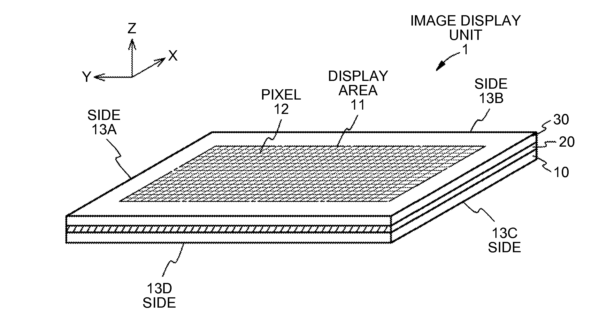
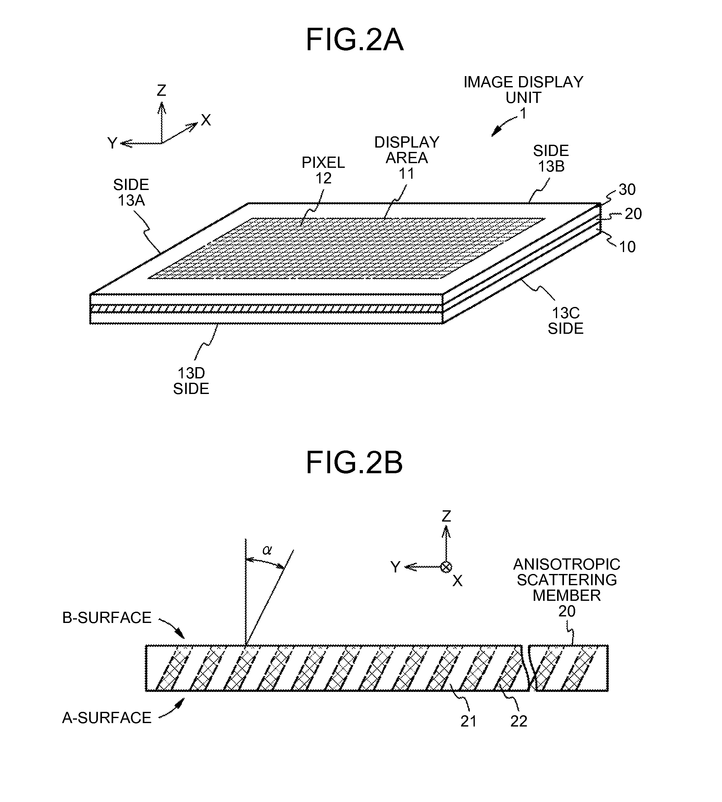
[0062]FIG. 2A is a schematic perspective view for explaining the configuration of the reflective image display unit. FIG. 2B is a schematic sectio...

second embodiment

[0104]A second embodiment also relates to a display device according to the present disclosure.

[0105]The second embodiment is different from the first embodiment in that an anisotropic scattering member is arranged so as to scatter external light incident from the outside while the light is passing through the anisotropic scattering member.

[0106]A display device 200 according to the second embodiment has the same configuration as that of the first embodiment except for the arrangement of the anisotropic scattering member. Because the image display unit 1 in FIG. 1 can be considered as an image display unit 2 and the display device 100 can be considered as the display device 200, a schematic perpendicular view of the display device 200 according to the second embodiment is not given. Because the image display unit 1 can be considered as the image display unit 2 by changing the arrangement of the anisotropic scattering member 20 in FIG. 2A as appropriate, a schematic perpendicular vie...

third embodiment

[0114]A third embodiment also relates to a display device according to the present disclosure.

[0115]The third embodiment is different from the first embodiment in that an anisotropic scattering member is formed by laminating a plurality of scattering members having different scattering characteristics.

[0116]A display device 300 according to the third embodiment has the same configuration as that of the first embodiment except for the structure of the anisotropic scattering member. Because the image display unit 1 in FIG. 1 can be considered as an image display unit 3 and the display device 100 can be considered as the display device 300, a schematic perpendicular view of the display device 300 according to the third embodiment is not given. Because the image display unit 1 can be considered as the image display unit 3 by changing the anisotropic scattering member 20 in FIG. 2A as appropriate, a schematic perpendicular view for explaining the configuration of the image display unit 3...


PUM

PropertyMeasurementUnit
scattering angleaaaaaaaaaa
refractive indexaaaaaaaaaa

Abstract

A display device includes a reflective image display unit having a sheet-like anisotropic scattering member. The sheet-like anisotropic scattering member has a surface in which both a low refractive index area and a high refractive index area exist. The sheet-like anisotropic scattering member is disposed so that a light enters from a first surface thereof and exits as scattered light from a second surface thereof, when an extent of refractive index difference at a boundary or vicinity thereof between the low refractive index area and the high refractive index area is relatively large in the first surface and relatively small in the second surface.

Description

CROSS REFERENCES TO RELATED APPLICATIONS[0001]The present application claims priority to Japanese Priority Patent Application JP 2013-005817 filed in the Japan Patent Office on Jan. 16, 2013, the entire content of which is hereby incorporated by reference.BACKGROUND[0002]1. Field of the Invention[0003]The present disclosure relates to a display device, and more specifically to a display device including an image display unit provided with a sheet-like anisotropic scattering member.[0004]2. Description of the Related Art[0005]There is known a reflective image display unit that displays an image by controlling the reflection ratio of external light or incident light. A reflective liquid crystal display panel, for example, includes a reflecting electrode that reflects incident light. The reflective liquid crystal display panel displays an image by controlling the reflection ratio of incident light with a liquid crystal material layer. Since a display device including such a reflective ...

Claims


Application Information

Patent Timeline
Patent Type & Authority Applications(United States)
IPC IPC(8): G02F1/1335
CPCG02F1/133504G02F1/13363G02F2203/02G02F1/133638G02B5/0257G02B5/0278G02F1/133553G02F1/133555
Inventor TAMAKI, MASAYAMITSUI, MASASHIFUKUNAGA, YOKO
Owner JAPAN DISPLAY INC
Why Eureka
Try Eureka