
Computer device and boot method thereof

a computer and boot method technology, applied in the field of computer devices and boot methods thereof, can solve the problems of longer boot time, limited start speed of the computer, ineffective increase, etc., and achieve the effect of shortening the boot tim

Active Publication Date: 2014-07-17
WISTRON CORP
View PDF5 Cites 13 Cited by
  • Summary
  • Abstract
  • Description
  • Claims
  • Application Information

AI Technical Summary

Benefits of technology

The patent text describes a method to quickly change the hardware element on a computer without having to open the chassis. This is done by writing marking information on the memory through the BIOS marking method. This allows the computer to quickly detect and respond to changes in hardware without having to perform a full hardware re-scanning and re-detection. This results in a faster boot time for the computer and improved user experience.

Problems solved by technology

As a result, it takes a lot of time to perform hardware scanning and detection, so that the boot time is longer than that acceptable to a user, and the start speed of the computer is limited and cannot be effectively increased.
However, after withdrawing from the setting interface of the BIOS and re-entering a boot process, it usually takes a lot of time to perform hardware re-scanning and re-detection, so that the boot time is longer than that acceptable to a user, and the start speed of the computer is limited and cannot be effectively increased.

Method used


Image

  • Computer device and boot method thereof
  • Computer device and boot method thereof
  • Computer device and boot method thereof

Examples


first embodiment

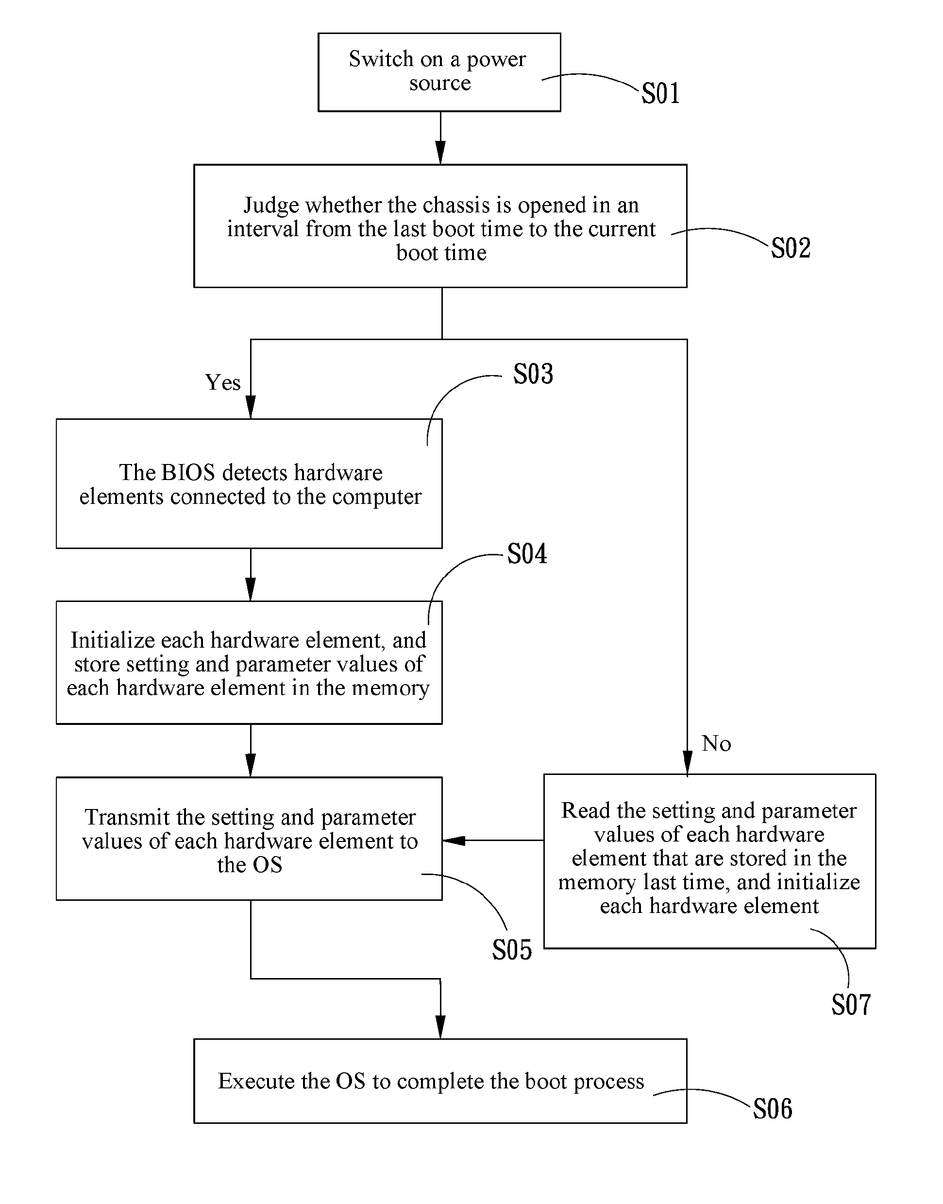
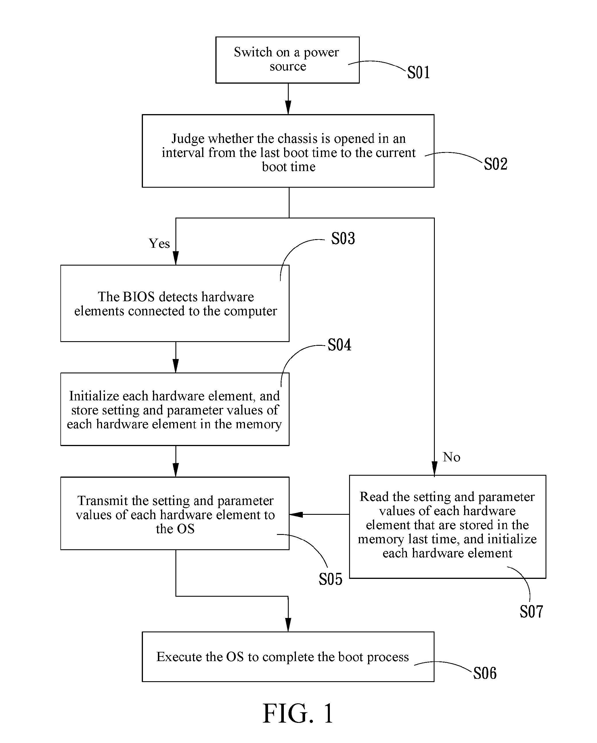
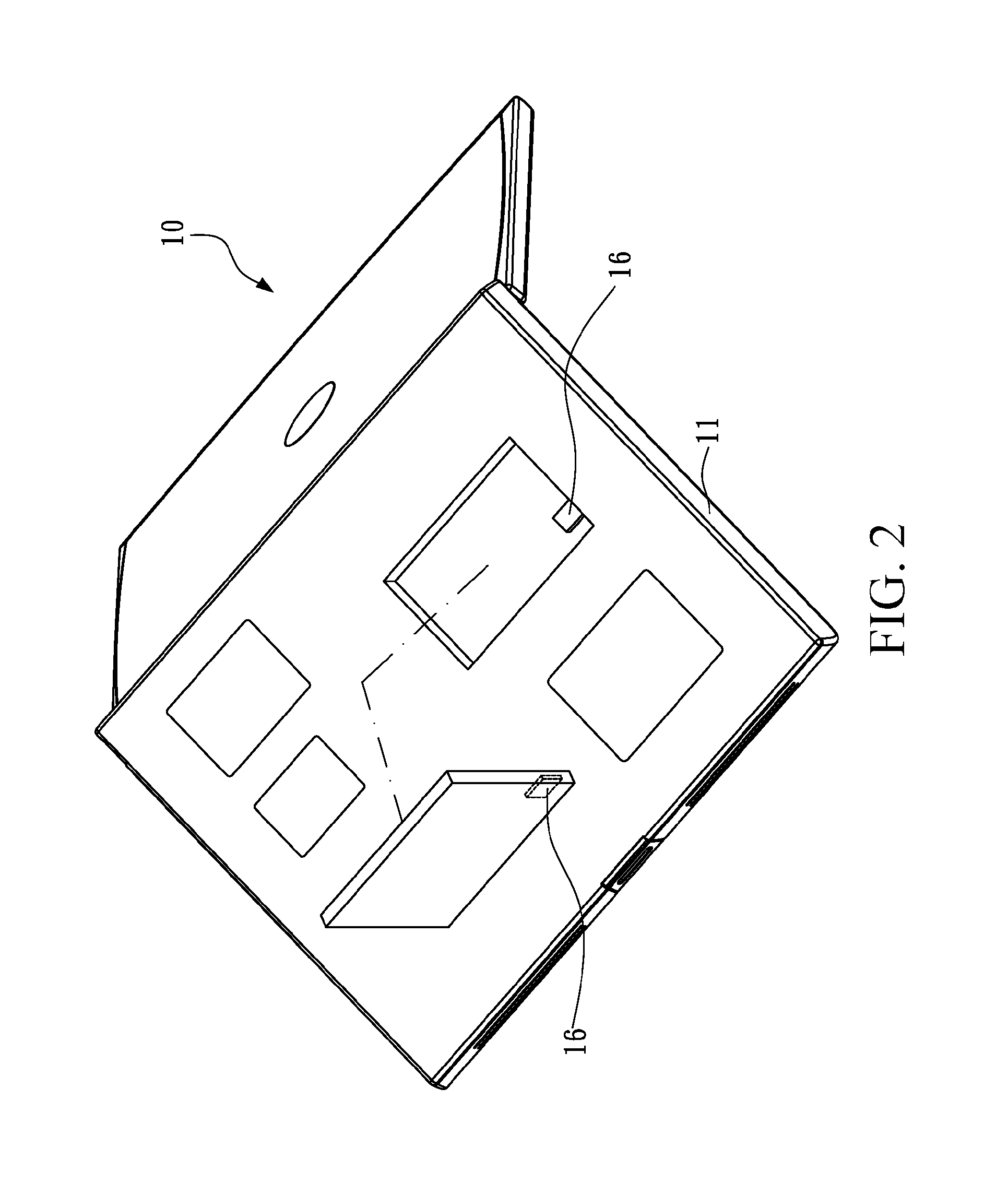
[0025]FIG. 1 is a flow chart of a boot method of a computer system according to the present invention, FIG. 2 is a rear view of a computer, and FIG. 3 is a schematic architectural view of the computer. Please refer to FIG. 1 to FIG. 3, in which the disclosed method is applicable to a computer 10 with a BIOS 13 and an OS 14, the computer 10 including a chassis 11, a memory, and an auxiliary power source 15. The method includes the following steps.

[0026]Step S01: Switch on a power source.

[0027]A power button of the computer is pressed to switch on the power source, so that the power source supplies power to each hardware apparatus for operation.

[0028]Step S02: Judge whether the chassis is opened in an interval from the last boot time to the current boot time.

[0029]After the power source is switched on, the computer 10 judges whether the chassis 11 is opened in the interval from the last boot time to the current boot time. If the chassis 11 of the computer 10 is opened in the interval ...

fourth embodiment

[0047]Please refer to FIG. 7 and FIG. 8. FIG. 7 is a flow chart of a BIOS marking method of a computer system according to the present invention, and FIG. 8 is a schematic architectural view of a computer in this embodiment. The disclosed method of this embodiment is applicable to a computer 10 with a BIOS 13 and an OS 14, the computer 10 including a memory 22. The method includes the following steps.

[0048]Step S11: Switch on a power source.

[0049]A power button of the computer 10 is pressed to switch on the power source, so that the power source supplies power to each hardware apparatus for operation.

[0050]Step S12: Judge whether the setting of a hardware element in the BIOS is changed.

[0051]After the power source is switched on, the computer 10 first judges whether the setting of any hardware element in the BIOS 13 is changed. If the setting of any hardware element in the BIOS 13 of the computer 10 is changed, Step S13 is performed. If the setting of no hardware element in the BIOS...


PUM


Abstract

A computer device and a boot method thereof are provided. The method is applicable to a computer with a Basic Input Output System (BIOS) and an Operating System (OS). The computer includes a chassis and a memory. In the boot method, after the computer is started, it is judged whether the chassis is opened in an interval from the last boot time to the current boot time. If the chassis is not opened in the interval from the last boot time to the current boot time, the BIOS does not detect hardware elements connected to the computer to obtain setting and parameter values of each hardware element, but reads directly the setting and parameter values of each hardware element that are stored in the memory last time, initializes each hardware element, transmits the setting and parameter values to the OS, and executes the OS to complete the boot process.

Description

CROSS-REFERENCES TO RELATED APPLICATIONS[0001]This non-provisional application claims priority under 35 U.S.C. §119(a) on Patent Application No. 102101677 filed in Taiwan, R.O.C. on 2013, Jan. 16, the entire contents of which are hereby incorporated by reference.BACKGROUND[0002]1. Technical Field[0003]The present invention relates to a computer device and a boot method thereof, and in particular, to a computer device and a boot method thereof capable of shortening the boot time.[0004]2. Related Art[0005]Once a computer is started, a Basic Input / Output System (BIOS) in the computer executes a series of instructions, such as detecting basic hardware elements mounted on a main board, reading information in a memory and judging whether the operation is normal, and detecting information of apparatuses connected to connection ports of the computer main board, and then stores and displays the information on a display screen, for a user to learn about the current state of the computer. If t...

Claims


Application Information

Patent Timeline
IPC IPC(8): G06F9/44
CPCG06F9/4406G06F9/4403G06F9/4411G06F9/4418
Inventor CHAO, SHU-LIN
Owner WISTRON CORP
Learn More