Motor vehicle door lock

Active Publication Date: 2014-07-24
KIEKERT & KOMMANDITGES
View PDF16 Cites 15 Cited by
  • Summary
  • Abstract
  • Description
  • Claims
  • Application Information

AI Technical Summary

Benefits of technology

[0020]As a result, the invention provides a motor vehicle door lock that, in particular as regards the “electric opening” function, provides a significant additional level of safety. Even unintentional electric opening processes are not translated into an opening of the l

Problems solved by technology

Consequently unintentional opening of the locking mechanisms is ruled out, as in this case the anti-th

Method used


Image

  • Motor vehicle door lock
  • Motor vehicle door lock
  • Motor vehicle door lock

Examples


Embodiment Construction

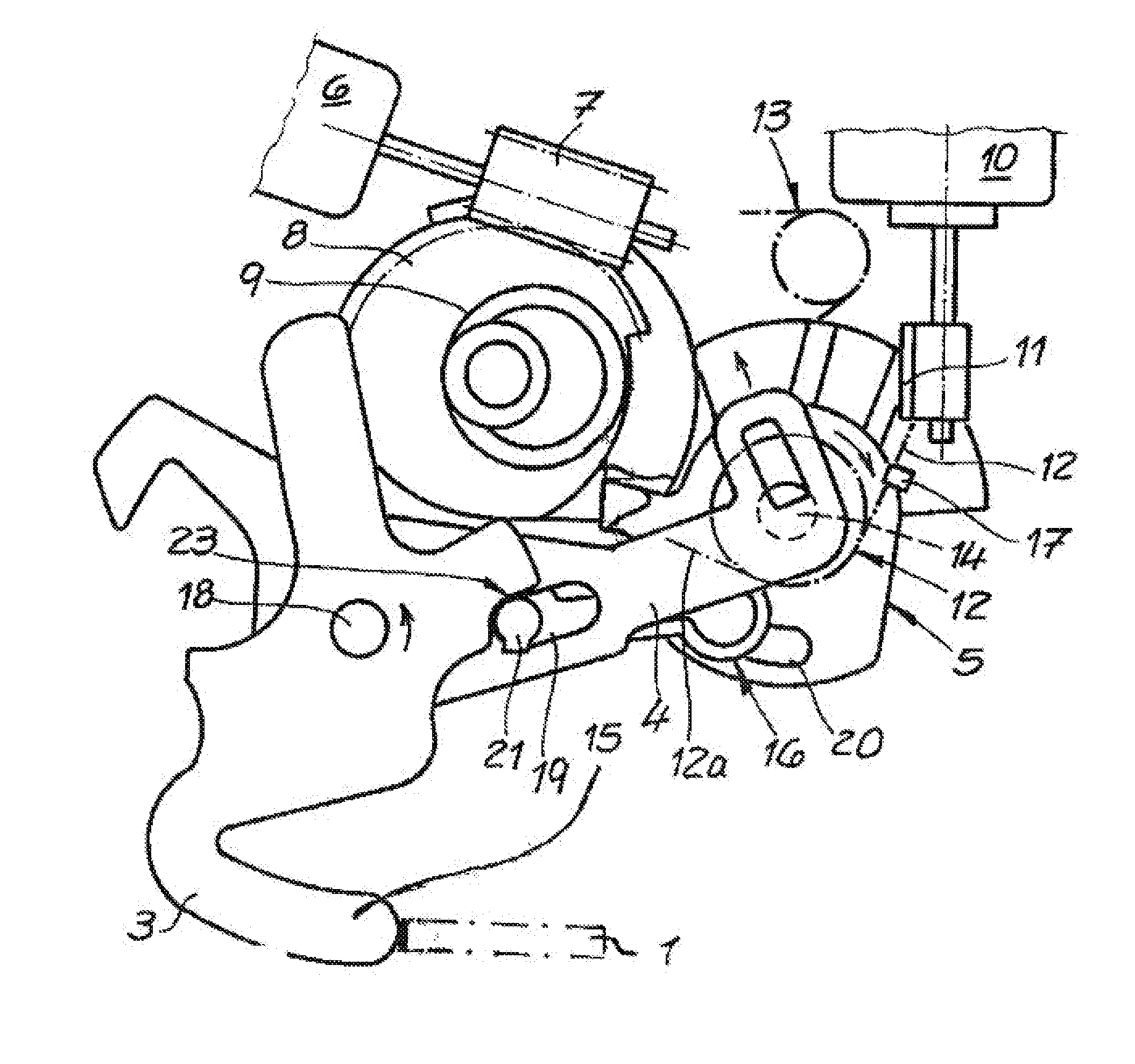
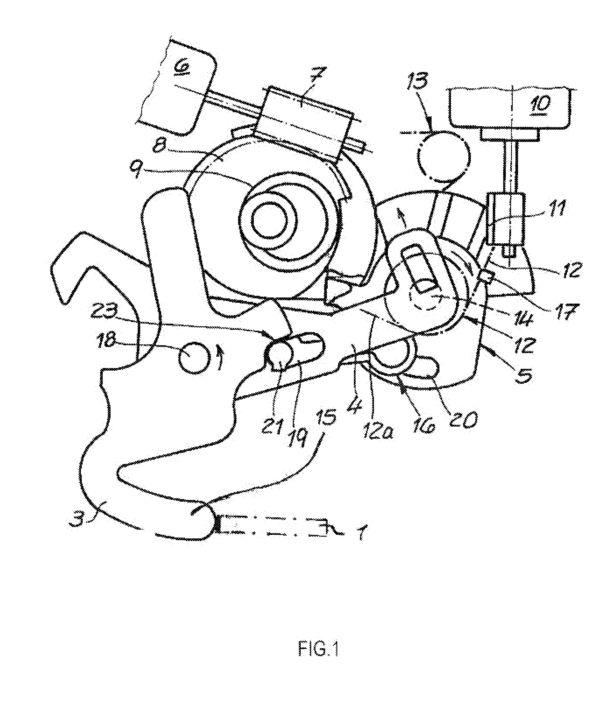
[0027]FIG. 1 shows a motor vehicle door lock equipped with a locking mechanism 1, 2, only indicated in the figure. Indeed all figures do show a pawl 1, interacting with a rotary latch 2 in the usual manner but which is not expressly shown. This is because the pawl 1 and the rotary latch 2 are located together in a plane vertical to the shown planes of projection. An actuating lever unit 3, 4, 16, comprising in detail a release lever 3, an internal release lever 4 and a coupling lever 16, interacts with the locking mechanism 1, 2 and said unit then interacts with an unlocking lever 5 in the example. The arrangement can in principle contain even more levers, such as an external release lever, another coupling lever, etc., which are however not shown and are of no significance for the described invention. The figure also shows a drive6 to 9, impinging on the actuation lever unit 3, 4, 16. Finally, the general arrangement contains an anti-theft protection device 10, 11.

[0028]As part of ...


PUM


Abstract

A motor vehicle door lock comprising a locking mechanism (1, 2), an actuating lever unit (3, 4, 16), which interacts with the locking mechanism (1, 2), a drive (6, 7, 8, 9) impinging upon the actuating lever unit (3, 4, 16) and an anti-theft protection device (10, 11), wherein a buffer member (12, 13) is assigned to the actuating lever unit (3, 4, 16) and to an unlocking lever (5) which interacts with the actuating lever unit (3, 4, 16), the buffer member being controlled by the anti-theft protection device (10, 11) in accordance with the desired functional position of the locking mechanism (1, 2).

Description

FIELD OF THE INVENTION[0001]The invention relates to a motor vehicle door lock equipped with a locking mechanism, an actuating lever unit which interacts with the locking mechanism also a drive impinging on the actuating lever unit and an anti-theft protection device.BACKGROUND OF THE INVENTION[0002]Such motor vehicle door locks are known from practical application and are, for instance, described in DE 10 2004 002 756 A1. As usual, the anti-theft protection device serves to deactivate the actuating lever mechanically connected to the locking mechanism during an impingement of the actuating lever unit by an internal release lever and during activation by an external release lever. This ensures that even if, for instance, the window has been smashed, unauthorized persons could not open the motor vehicle door using the internal release lever. This applies if the anti-theft protection device is active. The device is then in the position “Anti-theft protection on”.[0003]If the motor veh...

Claims


Application Information

Patent Timeline
IPC IPC(8): E05B77/44E05B47/02
CPCE05B47/023E05B77/44E05B77/28E05B81/06E05B81/14E05B2047/0031E05B81/34Y10T292/108E05B81/00E05B81/04
Inventor BARMSCHEIDT, CHRISTIAN
Owner KIEKERT & KOMMANDITGES
Why Eureka
Try Eureka