Motor and disk drive apparatus

Active Publication Date: 2014-07-24
NIDEC CORP
View PDF4 Cites 2 Cited by
  • Summary
  • Abstract
  • Description
  • Claims
  • Application Information

AI Technical Summary

Problems solved by technology

This makes it impossible to obtain the torque required in rotating the disk attached to the hub.
However

Method used


Image

  • Motor and disk drive apparatus
  • Motor and disk drive apparatus
  • Motor and disk drive apparatus

Examples


Example

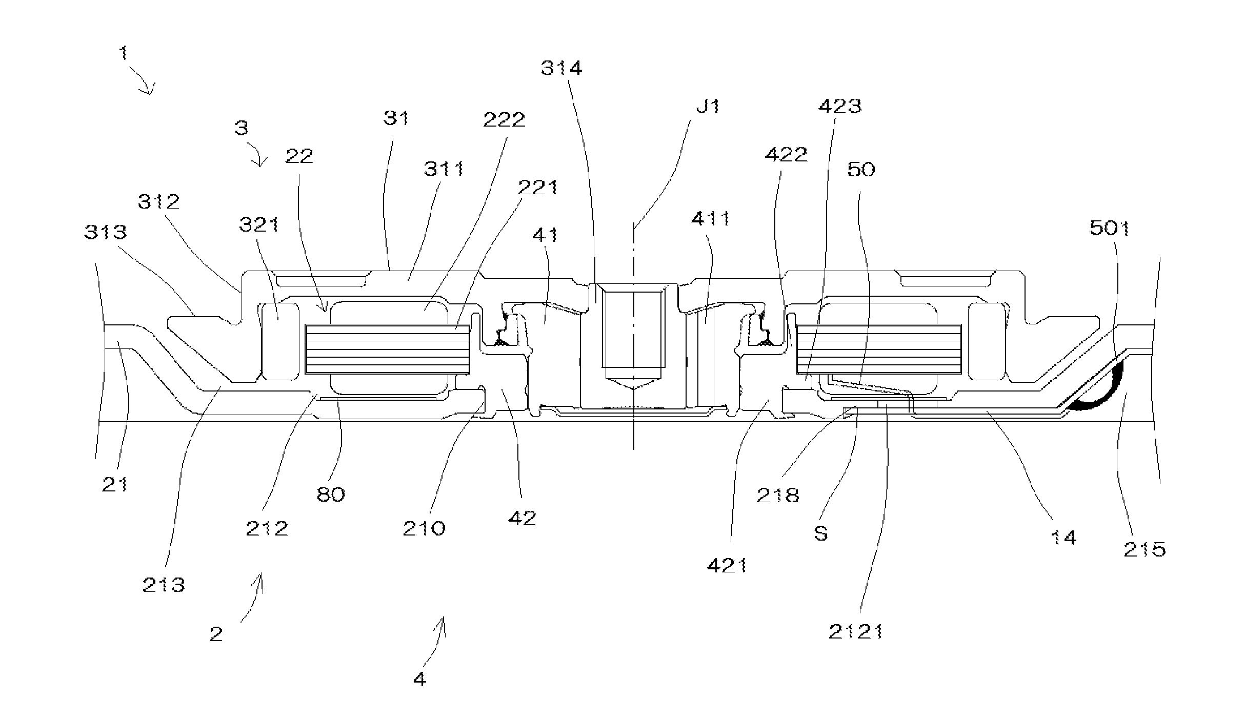
[0024]In the subject specification, the upper side in FIG. 1 along a center axis direction of a motor will be just referred to as “upper” and the lower side as “lower”. The up-down direction is not intended to indicate the positional relationship or the orientation when the motor is installed within an actual device. The direction parallel to the center axis will be referred to as “axial”. The radial direction about the center axis will be just referred to as “radial”. The circumferential direction about the center axis will be just referred to as “circumferential”.

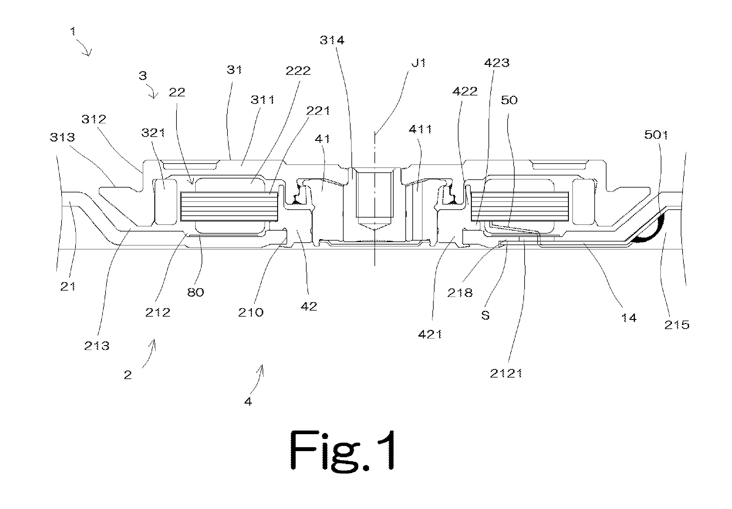
[0025]FIG. 1 is a section view of a spindle motor 1 according to one illustrative embodiment of the present invention. In the following description, the spindle motor 1 will be just referred to as “motor 1”. The motor 1 is used in a 2.5 inch-type disk drive apparatus (e.g., a hard disk drive apparatus) having a thickness of 7 mm or less or a thickness of 5 mm or less. The disk drive apparatus preferably includes a motor 1...


PUM


Abstract

A motor for use in a disk drive apparatus includes a bearing, a rotary unit, a stator, a thin flat base member, and a cylindrical holder extending in an axial direction. The base member includes a first through-hole, a peripheral edge portion, and a thin portion. The thin portion is located radially outward of the peripheral edge portion. The thin portion has an axial thickness smaller than an axial thickness of the peripheral edge portion. The holder includes a first protrusion portion and a second protrusion portion. The first protrusion portion extends radially outward and is located axially above the peripheral edge portion. The second protrusion portion extends radially outward and is located axially below the peripheral edge portion. The bearing is located inside the holder. A stator core is located radially outside the holder and axially above the thin portion.

Description

BACKGROUND OF THE INVENTION[0001]1. Field of the Invention[0002]The present invention relates to a motor and a disk drive apparatus.[0003]2. Description of the Related Art[0004]Conventionally, a disk drive apparatus such as a hard disk drive apparatus or the like is equipped with a spindle motor for rotating a disk. The disk drive apparatus includes a disk, a housing, a stator, a FPC (Flexible Printed Circuit), and so forth. The housing includes a cover member, a base member, and so forth.[0005]In recent years, the disk drive apparatus is required to become smaller in height and size. Particularly, for the sake of further reducing the height of a 2.5 inch-type 7 mm-thick disk drive apparatus which belongs to small-size disk drive apparatuses, it is necessary to reduce the thickness of a motor arranged within the housing. In general, the motor includes a hub, a coil, a stator core, a wiring substrate, a base member, etc. When assembling the motor, these components are arranged to axi...

Claims


Application Information

Patent Timeline
IPC IPC(8): H02K5/16
CPCH02K5/16H02K1/187H02K3/522G11B19/2009
Inventor MATSUMOTO, TAKUROYAWATA, ATSUSHI
Owner NIDEC CORP
Why Eureka
Try Eureka