
Cloaked electromagnetic field sensor

a field sensor and electromagnetic field technology, applied in the field of electromagnetic field testing, can solve the problems of distortion of the electromagnetic field being measured, affecting the accuracy of measurements, and devices and systems for measuring electromagnetic field have known limitations, so as to reduce the signature of the field sensor

Inactive Publication Date: 2014-07-24
THE UNITED STATES OF AMERICA AS REPRESENTED BY THE SECRETARY OF THE NAVY
View PDF1 Cites 1 Cited by
  • Summary
  • Abstract
  • Description
  • Claims
  • Application Information

AI Technical Summary

Benefits of technology

The patent text describes a way to make a sensor that reduces its impact on the electromagnetic field being measured. It does this by using a cloak that surrounds the sensor and creates a barrier to minimize interference. Multiple sensors can be placed together to create an array for more accurate measurements. The sensor can be passive or low-loss, meaning it doesn't affect the electromagnetic field it's measuring.

Problems solved by technology

Devices and systems for measuring an electromagnetic (EM) field have known limitations.
For example, the field sensors, cables, and electronic devices used to take the measurements can cause distortions in the EM field being measured.
These changes can affect the accuracy of the measurements and even interfere with the proper functioning of the device generating the EM field.
However, functional and manufacturing constraints place limitations on how small the electronic devices used with fiber optic links and out-of-band RF may be made, and the reduction in interference using these methods is therefore limited.
No method or apparatus known in the art significantly reduces the signature of the field sensor and the transmitter conduit operatively connected to it.

Method used


Image

  • Cloaked electromagnetic field sensor
  • Cloaked electromagnetic field sensor
  • Cloaked electromagnetic field sensor

Examples


Embodiment Construction

[0022]For the purpose of promoting an understanding of the present invention, references are made in the text to exemplary embodiments of a cloaked field sensor apparatus and a method to cloak aspects of a field sensor, only some of which are described herein. It should be understood that no limitations on the scope of the invention are intended by describing these exemplary embodiments. One of ordinary skill in the art will readily appreciate that alternate but functionally equivalent materials, components, and placement may be used. The inclusion of additional elements may be deemed readily apparent and obvious to an artisan of ordinary skill. Specific elements disclosed herein are not to be interpreted as limiting, but rather as a basis for the claims and as a representative basis for teaching one of ordinary skill in the art to employ the present invention.

[0023]It should be understood that the drawings are not necessarily to scale; instead emphasis has been placed upon illustra...


PUM


Abstract

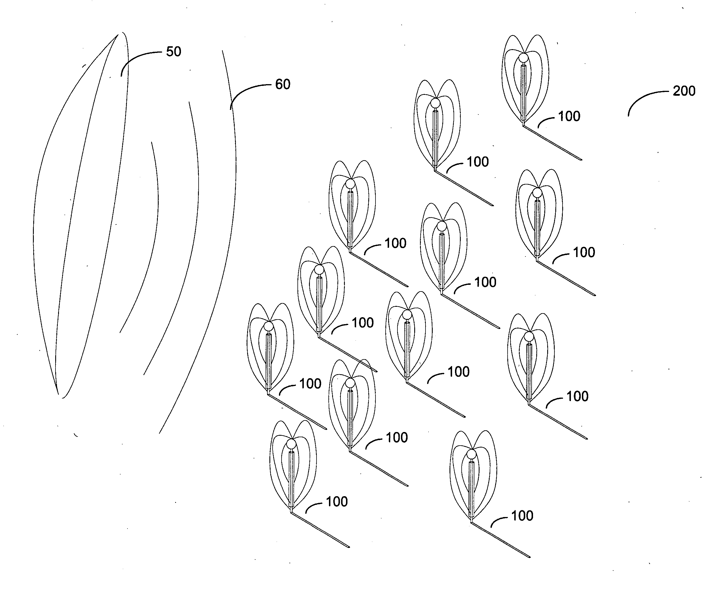
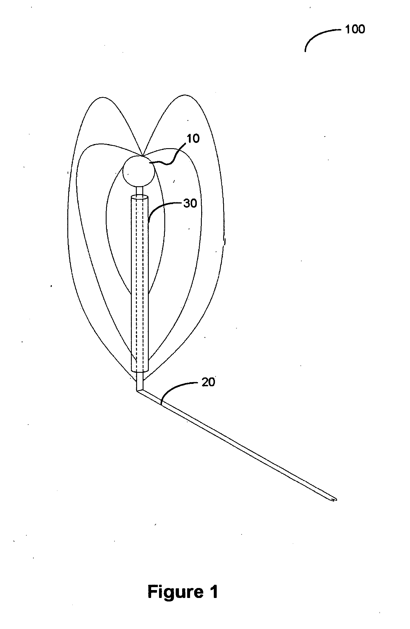
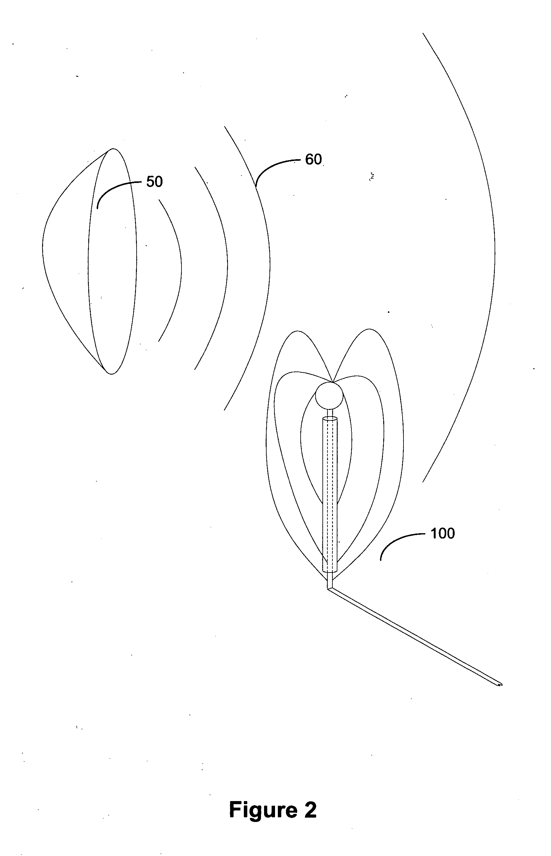
A cloaked field sensor apparatus and system using a cloaking barrier sheath to substantially enclose the surface of a transmitter conduit exposed to an electromagnetic field being measured to reduce the field sensor's interference with the electromagnetic field being measured. Multiple cloaked field sensor apparatuses may be aligned in an array and use identical or different cloaking barrier sheaths.

Description

STATEMENT OF GOVERNMENT INTEREST[0001]The invention described herein was made in the performance of official duties by one or more employees of the Department of the Navy, and the invention herein may be manufactured, practiced, used, and / or licensed by or for the Government of the United States of America without the payment of any royalties thereon or therefor.FIELD OF THE INVENTION[0002]The present invention relates to the field of electromagnetic testing and more specifically to an apparatus and system to more accurately measure the actual strength of electric or magnetic fields without altering the field being measured.BRIEF DESCRIPTION OF THE DRAWINGS[0003]FIG. 1 illustrates an exemplary embodiment of a cloaked field sensor apparatus.[0004]FIG. 2 illustrates an exemplary embodiment of a cloaked field sensor apparatus in conjunction with an electromagnetic source that emits an electromagnetic field.[0005]FIG. 3 illustrates an exemplary embodiment of multiple cloaked field senso...

Claims


Application Information

Patent Timeline
IPC IPC(8): G01R29/00
CPCG01R29/0878H01Q1/521
Inventor SESSIONS, WALTER D.BOULAIS, KEVIN A.ROAMES, JENNIFER K.
Owner THE UNITED STATES OF AMERICA AS REPRESENTED BY THE SECRETARY OF THE NAVY
Learn More