
Multi-spectral air inlet shield and associated inlet structure

Active Publication Date: 2006-04-06
TEMEKU TECH +1
View PDF12 Cites 7 Cited by
  • Summary
  • Abstract
  • Description
  • Claims
  • Application Information

AI Technical Summary

Benefits of technology

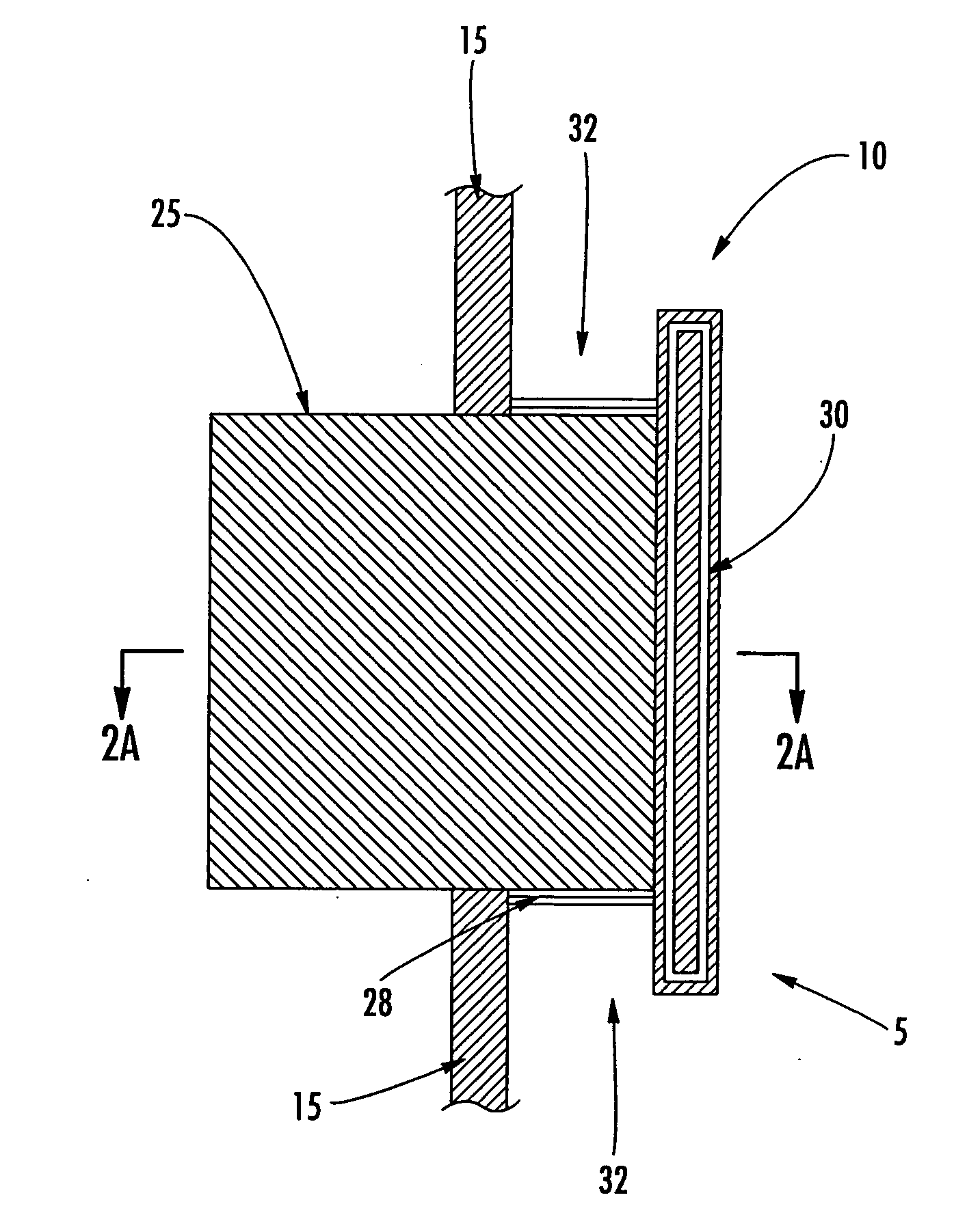
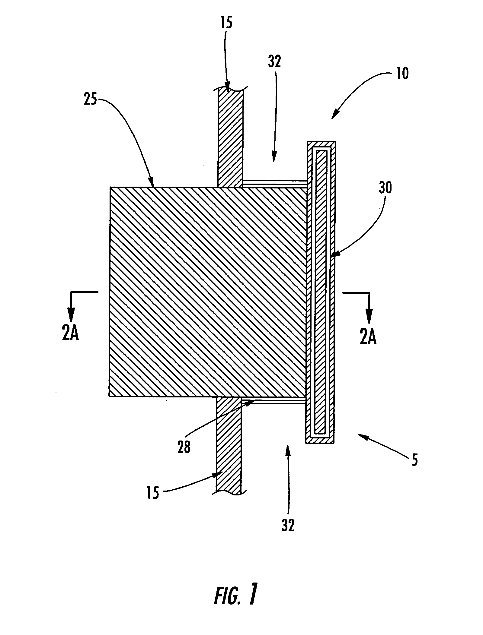
[0010] The present invention provides a multi-spectral air inlet shield and associated inlet structure for reducing the relative radar and infrared observability of commercial or private ships, naval vessels, or other air-breathing applications such as land-based vehicles, missiles and / or satellites. Specifically, the improved shield reduces the signature projected by air inlet ports across multiple spectrums including radar and infrared wavelengths. Air inlet ports, as described herein, refer to those ports disposed within the exterior wall of the above referenced vehicles that deliver air to various onboard systems. These systems may include, various gasoline, diesel or nuclear propulsion systems, HVAC systems, or other similar systems.
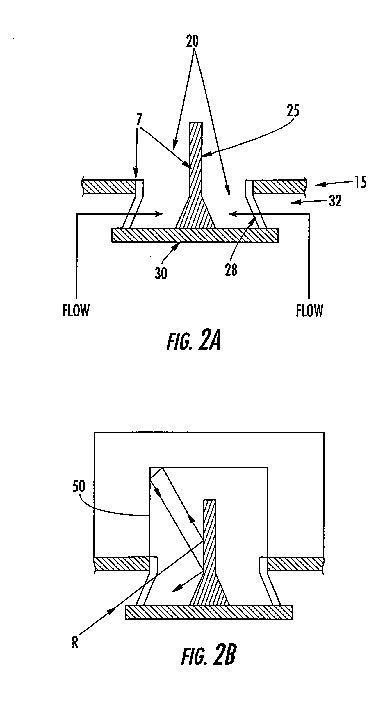
[0012] The splitter and / or at least one support secures the plate a distance in front of the air inlet port so as to form a channel around at least a portion of the plate. The desired air stream then passes behind the plate and into the air inlet port. By shielding the air inlet port with the plate as discussed above, air may be provided to appropriate onboard systems while eliminating line-of-sight interrogation of the inlet ports by enemy radar and infrared detection systems.
[0015] According to another embodiment, the multi-spectral shield may include infrared suppression materials forming at least one visible surface of the plate, the splitter, or at least one support. Such materials further reduce the inlet port's observability by absorbing infrared radiation generally emitted by the hot internal components found within many air inlet ports. Such materials are used to reduce the observability of areas of high temperature contrast that are commonly targeted by enemy detection systems. In addition, at least one of the air inlet port, the at least one support, the splitter, and the plate may be physically structured to reduce specular infrared reflections produced by internal heatable components.
[0017] In another embodiment, the air inlet port may be disposed within a recessed portion of an exterior wall. According to this embodiment the exterior surface of the plate is positioned substantially planar to the non-recessed portion of the exterior wall, thereby preventing significant alteration of the lateral radar cross section of the vehicle.
[0018] According to another embodiment, the air inlet port may be disposed within a recessed portion proximate a corner of an exterior wall. As with the above-described embodiment, in this embodiment the exterior surface of the plate is positioned substantially planar to the non-recessed portion of the exterior wall, thereby preventing any significant alteration of the lateral radar cross section of the vehicle.

Problems solved by technology

As detection systems have become more precise, it has become evident that louvers and / or screens present several problems.
Unfortunately, in many cases the design of the louver and screen requires a radar coating so thin that its overall effectiveness is limited.
Another problem associated with louvers and screens is the fact that each is supported within the air inlet port by a frame member.
Finally, screens in particular present a significant problem.
This results in a reflective surface for radar energy and further generates surface noise due to the wire geometry.
In addition, this mesh configuration makes it difficult to provide adequate infrared signature treatment and reduces the air flow efficiency of the inlet port.

Method used


Image

  • Multi-spectral air inlet shield and associated inlet structure
  • Multi-spectral air inlet shield and associated inlet structure
  • Multi-spectral air inlet shield and associated inlet structure

Examples


example embodiment

[0047] In various embodiments, the present invention includes a multi-spectral shield wherein at least one of the plate, splitter, and / or the supports are appropriately sized and positioned relative to the air inlet port to ensure efficient operation of the vehicle's air breathing system (e.g., engine, HVAC system, etc.). In one example embodiment, a test air inlet structure was configured to feed a gas turbine engine (not shown). As will be apparent to one of skill in the art, gas turbine engines operate efficiently when fed by a uniform air flow having a total pressure drop of less than 4 inwg across the entire air inlet system. This total pressure drop includes any losses attributed to the inlet structure as well as any losses provided by ductwork or other internal obstructions. Accordingly, in various embodiments, the inlet structure components (i.e., the inlet port, the plate, the splitter, and the supports) must be configured such that the inlet structure does not unduly contr...


PUM

PropertyMeasurementUnit
Flow rateaaaaaaaaaa
Distanceaaaaaaaaaa
Reflectionaaaaaaaaaa

Abstract

A multi-spectral shield and associated inlet structure is provided for reducing the signature of an air inlet port defined within an exterior wall of an aircraft, ship, or land-based vehicle across radar and infrared wavelengths. The multi-spectral inlet shield includes a plate disposed in front of the air inlet port. The plate is sized to visibly eclipse the air inlet port, when viewed from a direction perpendicular to the plate. The plate is supported in this position by a plate mount or splitter that extends from within the air inlet port and attaches to the plate. A support may optionally combine with the splitter to support the plate in this position. Air passes behind the plate and into the air inlet port via a channel defined around at least a portion of the plate.

Description

FIELD OF THE INVENTION [0001] The present invention relates generally to reducing the radar and infrared detection of vehicles, and more particularly, to a multi-spectral air inlet shield and associated inlet structure for providing low radar and infrared signatures. BACKGROUND OF THE INVENTION [0002] The survivability of ships, modern military aircraft and other air vehicles such as missiles and satellites, and land-based vehicles may be traced, at least partially, to the relative observability of the vehicle to enemy detection systems. Principally, enemy detection systems rely on reflected radar waves and emitted infrared radiation to acquire and target military vehicles. Stealth technology and other methodologies were developed to defeat this acquisition and targeting capability by reducing a vehicle's overall radar cross section and infrared emissions. In response, counter-stealth technology was developed which yielded more precise detection systems that could isolate specific v...

Claims


Application Information

Patent Timeline
IPC IPC(8): B64C1/10
CPCB63G13/02F02C7/04F02K1/822F02K1/825F41H3/00H01Q1/528Y02T50/675Y10T137/0536Y02T50/60
Inventor MEANS, JAMES L.
Owner TEMEKU TECH
Learn More