Electromagnetic shielding composite comprising nanotubes

a technology of electromagnetic shielding and nanotubes, which is applied in the field of electromagnetic shielding composites containing nanotubes, can solve the problems of large need for electromagnetic shielding materials, loss of metals' inherent em shielding characteristics, and approach suffers from substantial drawbacks, and achieves the effect of low loading

Inactive Publication Date: 2009-05-21
GLATKOWSKI PAUL +4
View PDF6 Cites 2 Cited by
  • Summary
  • Abstract
  • Description
  • Claims
  • Application Information

AI Technical Summary

Benefits of technology

[0005]In an especially preferred aspect of this invention, the composite will have both high EM shielding properties and also low radar profile due to the high absorptiveness of the composites and correspondingly low reflectance to electromagnetic radiation.
[0012]In a further aspect, this invention relates to a method of lowering the radar observability of an object comprising partially or entirely surrounding said object with a layer of nanotubes according to the invention effective for lessening radar observability.
[0028]The immense flexibility of the composites of this invention make them suitable for a very wide array of applications. These include: EM shielding on any kind of equipment or enclosure having contents which are sensitive to EM radiation, especially high bursts, protection of electronics in enclosures, protection of electronic components from interference from one another on circuit boards, protection of computer systems housed within plastic cases from outside electromagnetic interferences, as well as protection of systems from emitted RF radiation from surrounding computers, such as airline navigation system from laptop computers, and automotive electronics. Typically, electronic machinery and enclosures containing life forms are especially helped by this invention.
[0030]A special advantage of this invention is that the amount of nanotube composite needed to achieve the given desired level of EM shielding is much less than for conventional materials. As noted above, amounts less than 1% by weight of nanotubes of a composite can be used, and even less, depending on the particular needs of the application. The composites also retain the other advantages of the underlying base resin such as weight reduction with increased strength.
[0033]The advantages of the EM shielding composite of the present invention include: commercial off-the-shelf availability of carbon nanotubes, ease of synthesis of nanotubes (of carbon or otherwise) low observability due to the low reflective power of less than about 16%, and the available low density of the shielding composite, e.g., 1.2-1.4 g / cm3. The low loading levels of nanotubes required by this invention are advantageous for both their economy, lack of degradation of the base polymer's structural properties, and compatibility with most conventional polymer processing techniques.

Problems solved by technology

The need for electromagnetic shielding materials is enormous.
However, with the replacement of metals by a wide variety of new materials, e.g. polymeric, there has been a loss of the metals' inherent EM shielding characteristics.
However, these approaches suffer from substantial drawbacks.

Method used


Image

  • Electromagnetic shielding composite comprising nanotubes

Examples


example 1

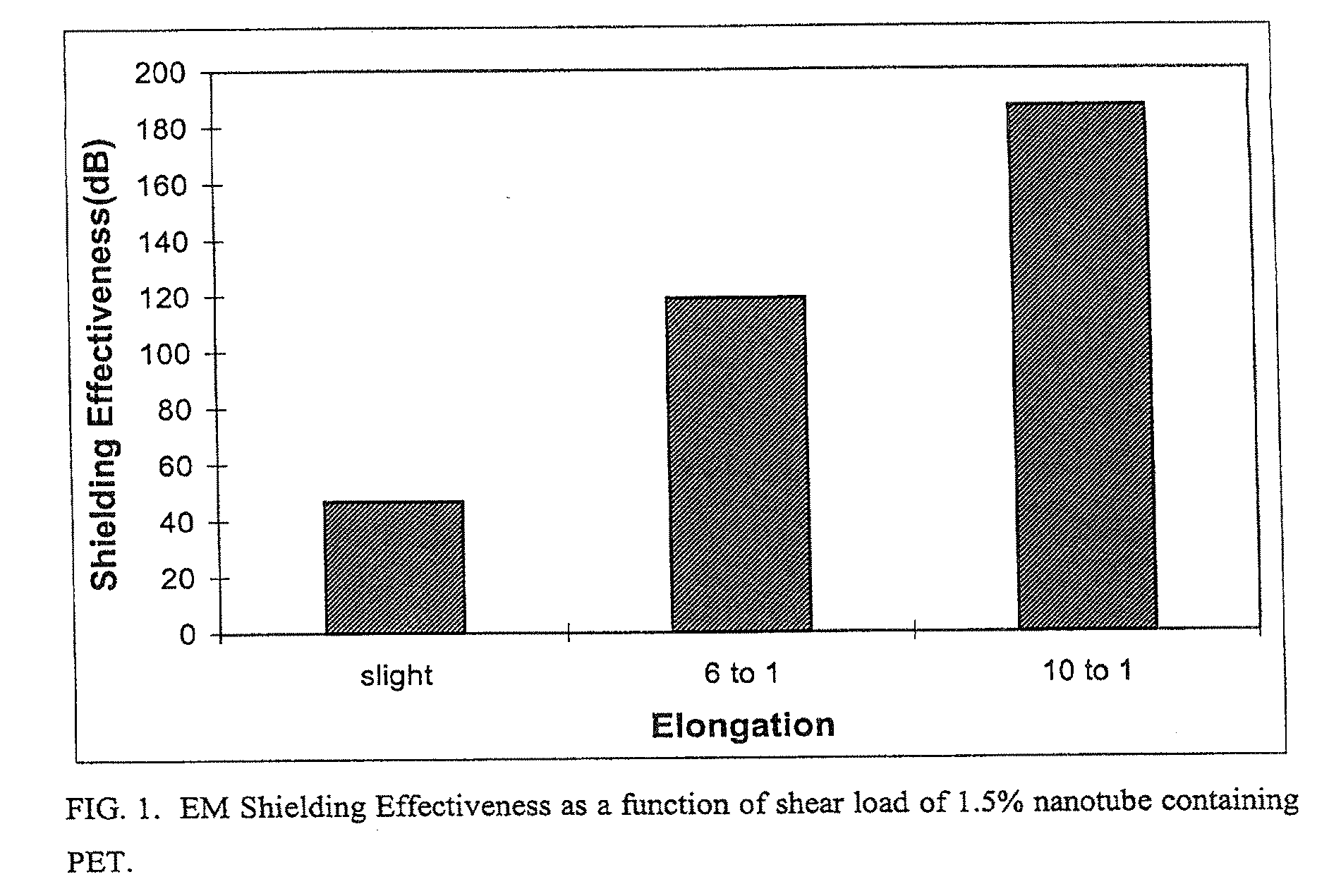
Electromagnetic Shielding Effectiveness (EMSE)

[0036]Five pounds of pelletized polyethylene terephthalate (PET) with fifteen weight percent Graphite Fibril™ nanotubes were produced by Hyperion Catalysis International. This Hyperion concentrate of 15 wt % carbon fibers in unspecified Eastman extrusion grade PET polyester resin was used as a master batch for let down (dilution) with neat Natural PET resin 0.85 IV Eastman natural PET. Both resins dried 4.5 hours at 290 F and kept in sealed glass bottles before use. The 1.5% carbon resin was a 9:1 blend of the concentrate and the neat resin by weight. 2:1 blends of concentrate with natural were made to reduce carbon content from 15% to 10% and again from 10% to 6.7%. In doing so, varying concentrations of nanotubes could be extruded for testing. The master batch and a letdown thereof to the plaque size required for EMI shielding testing were extruded along with a neat PET control.

[0037]A ¾ inch Brabender single screw extruder with an eng...

example 2

Dielectric Testing for Low Observability Correlation

[0052]In addition to the EMSE testing, dielectric testing to ASTM D2520 “Standard Text Test Methods for Complex Permittivity (Dielectric Constant) of Solid Electrical Insulating Materials at Microwave Frequencies and Temperatures to 1650° C.” was performed. This method uses a waveguide cavity to measure the material at microwave frequencies. The cavity measurement is the most accurate dielectric measurement available at microwave frequencies. Although cavities are designed for a discrete frequency, within the normal microwave range material dielectric properties do not change over frequency, and thus this measurement is fairly accurate for the range. This trend can be noted in the EMSE testing, where shielding effectiveness did not appreciable change over frequency sweep of 20 kHz to 1.5 GHz.

[0053]The cavity volume used was 0.960 cubic inches and the cavity (Q) equals 4308, based on ambient temperatures and typical test equipment s...


PUM

PropertyMeasurementUnit
frequenciesaaaaaaaaaa
lengthsaaaaaaaaaa
weight percentaaaaaaaaaa

Abstract

There is provided an electromagnetic (EM) shielding composite and its method of manufacture having low observability and a low loading level, e.g., 1.5 weight percent, of nanotubes mixed in a base host polymer, wherein the EM shielding composite is an effective shield and absorber for broadband plane wave EM radiation. The loading levels of nanotubes are sufficiently low to leave the mechanical properties of the base polymers essentially unchanged, making this approach widely applicable to a broad range of applications.

Description

FIELD OF THE INVENTION[0001]The present invention relates generally to electromagnetic (EM) radiation absorbing composites containing nanotubes.[0002]The need for electromagnetic shielding materials is enormous. Applications of EM shielding material are found in, for example, EM-sensitive electronic equipment, stealth vehicles, aircraft, etc., having low radar profiles, protection of electronic components from interference from one another on circuit boards, protection of computer equipment from emitting RF radiation causing interference to navigation systems, medical life support systems, etc. Metal shielding has long been known for these functions. However, with the replacement of metals by a wide variety of new materials, e.g. polymeric, there has been a loss of the metals' inherent EM shielding characteristics. Some attempts at improving the EM shielding characteristics of plastics have been made. However, these approaches suffer from substantial drawbacks. Thus, new and improve...

Claims


Application Information

Patent Timeline
Patent Type & Authority Applications(United States)
IPC IPC(8): G21F1/10
CPCG21F1/10Y10S977/742Y10S977/788Y10S977/753Y10S977/734Y10S977/847Y10S977/902
Inventor GLATKOWSKI, PAULMACK, PATRICKCONROY, JEFFREY L.PICHE, JOSEPH W.WINSOR, PAUL
Owner GLATKOWSKI PAUL
Why Eureka
Try Eureka