
Joining structure and insert-molded cover using same

a jointing structure and insert molding technology, applied in the direction of instruments, electrical apparatus casings/cabinets/drawers, instruments, etc., can solve the problems of easy loosening of the plastic antenna lid from the metallic body, thin metallic cover susceptible to cracking, and relatively compromised mechanical strength and durability of the metallic cover

Inactive Publication Date: 2009-11-12
HON HAI PRECISION IND CO LTD
View PDF1 Cites 21 Cited by
  • Summary
  • Abstract
  • Description
  • Claims
  • Application Information

AI Technical Summary

Benefits of technology

[0006]Because the metal has a good electromagnetic shielding capability, a portion of the cover corresponding to an antenna of an electronic device is made of plastic, so that signals can be received and transmitted through the plastic portion, and certain functions would not be weaken by electromagnetic shielding. Generally, the metallic cover includes a metallic body and a plastic antenna lid fixed to the metallic body by hook locking or rivet jointing. However, these fixing means easily leave a gap between the plastic antenna lid and the metallic body, such that the plastic antenna lid easily becomes loosened from the metallic body due to the gap. In addition, a thin metallic cover is susceptible to crack at the junction where the plastic antenna lid is fixed to the metallic body by hook locking or rivet jointing. Therefore, the mechanical strength and durability of the metallic cover is relatively compromised.

Problems solved by technology

However, these fixing means easily leave a gap between the plastic antenna lid and the metallic body, such that the plastic antenna lid easily becomes loosened from the metallic body due to the gap.
In addition, a thin metallic cover is susceptible to crack at the junction where the plastic antenna lid is fixed to the metallic body by hook locking or rivet jointing.
Therefore, the mechanical strength and durability of the metallic cover is relatively compromised.
Secondly, an adhesive is coated on a surface of the metallic body.
Thirdly, the adhesive is solidified to form an adhesive film on the surface of the metallic body.

Method used


Image

  • Joining structure and insert-molded cover using same
  • Joining structure and insert-molded cover using same
  • Joining structure and insert-molded cover using same

Examples


Embodiment Construction

[0017]Reference will now be made to the drawings to describe preferred embodiments of the present joining structure for joining a metallic portion and a plastic portion and insert-molded cover using the joining structure, in detail. The insert-molded cover is used for electronic devices such as notebook computers, and mobile phones.

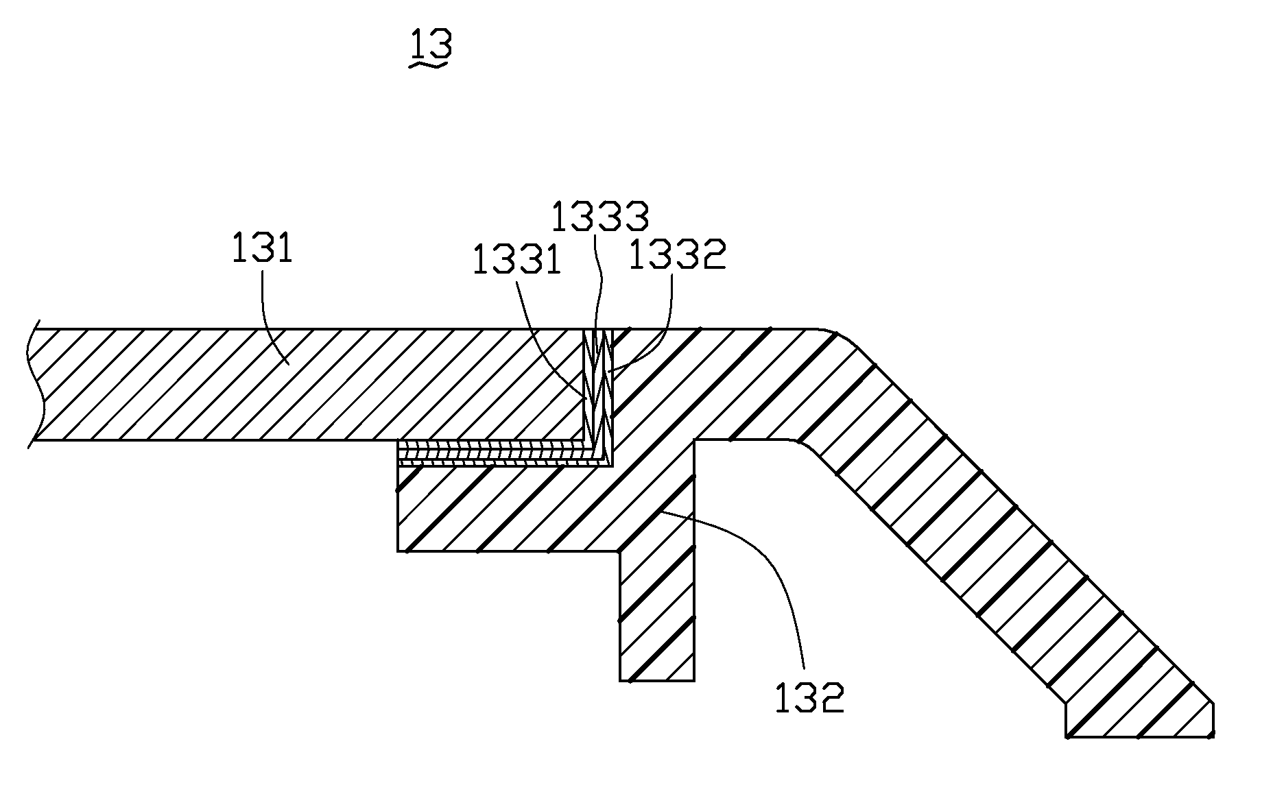
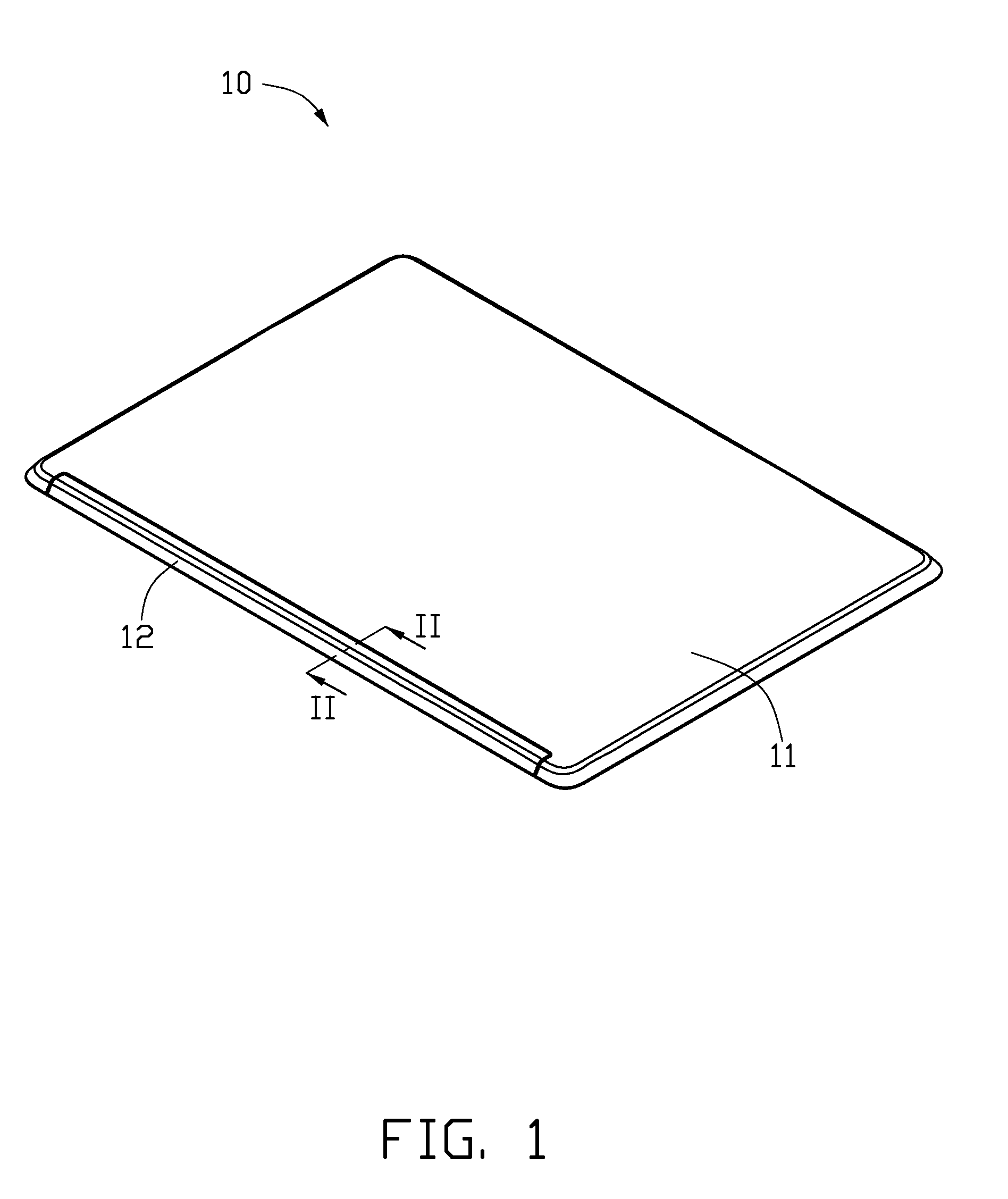
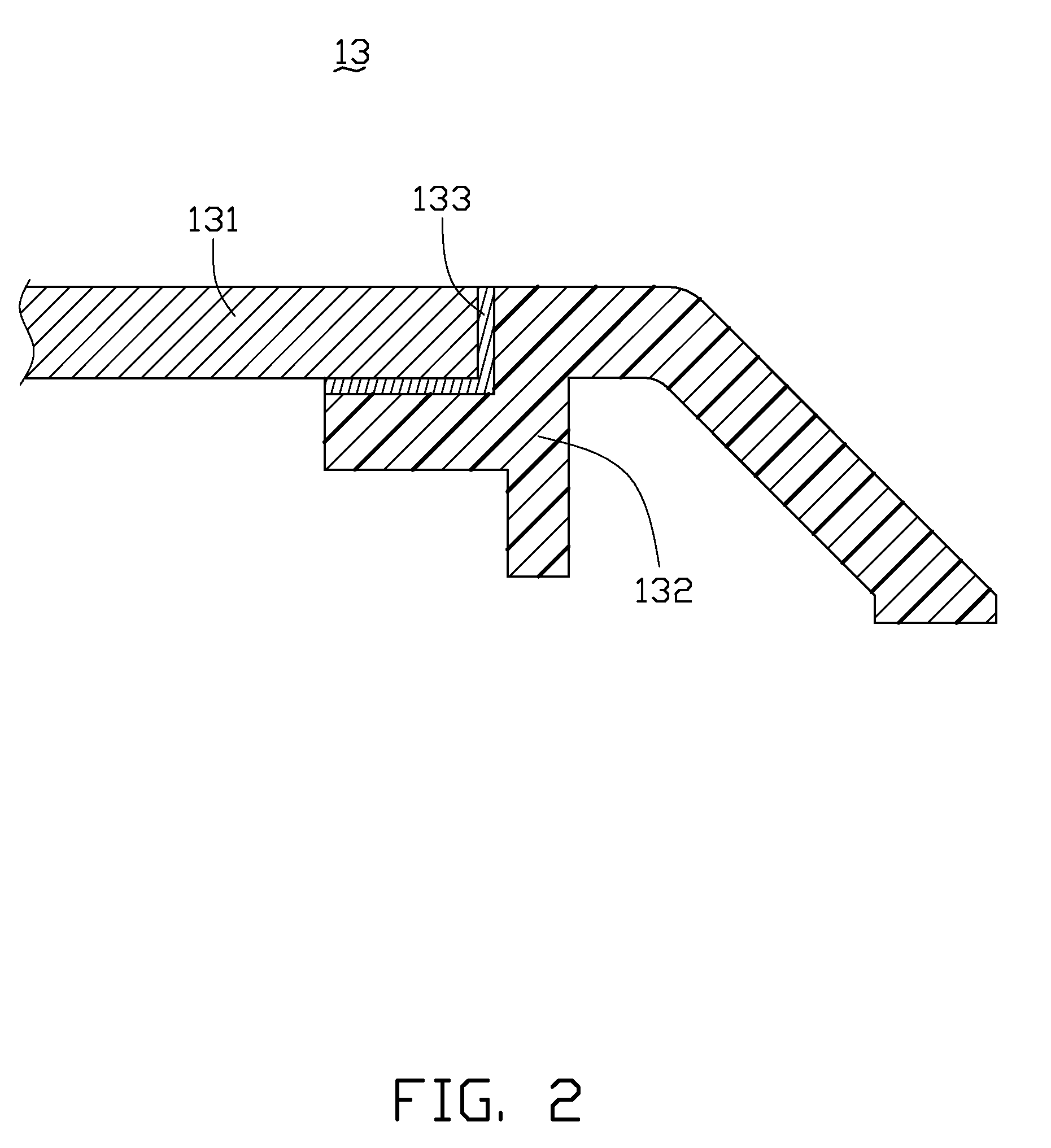
[0018]Referring to FIGS. 1 and 2, an insert-molded cover 10 for electronic devices according to a preferred embodiment is shown. The insert-molded cover 10 includes a metallic body 11 and a plastic antenna lid 12. The metallic body 11 and the plastic antenna lid 12 are joined together by a joining structure 13.

[0019]The metallic body 11 is substantially a rectangular plate made of alloy, and the alloy is preferably magnesium alloy, aluminum alloy or titanium alloy. In this preferred embodiment, the metallic body 11 is made of magnesium alloy.

[0020]The plastic antenna lid 12 is substantially an elongated sheet. The plastic antenna lid 12 is formed on an ed...


PUM

PropertyMeasurementUnit
Temperatureaaaaaaaaaa

Abstract

An exemplary joining structure, used for insert-molded covers, includes a metallic portion (131), a plastic portion (132) integrally formed with the metallic portion, and an adhesive film (133) formed between the metallic portion and the plastic portion. The metallic portion and the plastic portion are bonded together by the adhesive film. The present invention also relates an insert-molded cover (10) for electronic devices using the joining structure and a method for manufacturing the insert-molded cover for electronic devices.

Description

CROSS-REFERENCE TO RELATED APPLICATIONS[0001]This application is related to five co-pending U.S. patent applications, applications Ser. No. 12 / 171271, Ser. No. [to be advised] (Docket No. US20076), Ser. No. [to be advised] (Docket No. US20236), Ser. No. [to be advised] (Docket No. US20421), Ser. No. [to be advised] (Docket No. US20075), and all entitled “INSERT-MOLDED COVER AND METHOD FOR MANUFACTURING SAME”. In the co-pending applications, the inventors are Han-Ming Lee, Chih-Chien Hung, Hsiang-Sheng Chou and Ching-Hsien Chang. Such applications have the same assignee as the present application and have been concurrently filed herewith. The disclosures of the above identified applications are incorporated herein by reference.BACKGROUND OF THE INVENTION[0002]1. Field of the Invention[0003]The present invention relates generally to joining structures, more particularly, to a joining structure for joining a metallic portion and a plastic portion, and an insert-molded cover using the j...

Claims


Application Information

Patent Timeline
IPC IPC(8): B32B7/00B05D5/10B32B15/00B32B15/08
CPCG06F1/1616G06F1/1626G06F1/1656G06F1/1698Y10T428/26G06F2200/1633G06F2200/1634H05K5/0217G06F1/181Y10T428/31678Y10T428/31681
Inventor LEE, HAN-MINGHUNG, CHIH-CHIENCHOU, HSIANG-SHENGCHANG, CHING-HSIEN
Owner HON HAI PRECISION IND CO LTD
Learn More