Eureka AIR delivers breakthrough ideas for toughest innovation challenges, trusted by R&D personnel around the world.

Pluggable optical transceiver module

An optical transceiver module and a part of the technology, applied in the coupling of optical waveguides, electrical components, magnetic field/electric field shielding, etc., can solve problems affecting the electromagnetic shielding effect of optical modules

Inactive Publication Date: 2014-06-18
SHENZHEN NEOPHOTONICS TECH
View PDF5 Cites 24 Cited by
  • Summary
  • Abstract
  • Description
  • Claims
  • Application Information

AI Technical Summary

Problems solved by technology

[0005] For the electromagnetic shielding of conductor materials, it is best to use an integral metal shell to achieve the best effect. However, in practical applications, due to design and assembly requirements, there are few conductive connection points between the module base and the upper cover, and the optical component adapter shell and the base. Will greatly affect the electromagnetic shielding effect of the entire optical module

Method used


Image

  • Pluggable optical transceiver module
  • Pluggable optical transceiver module
  • Pluggable optical transceiver module

Examples


Embodiment Construction

[0021] The preferred embodiment of the present invention will be described in detail below in conjunction with the accompanying drawings.

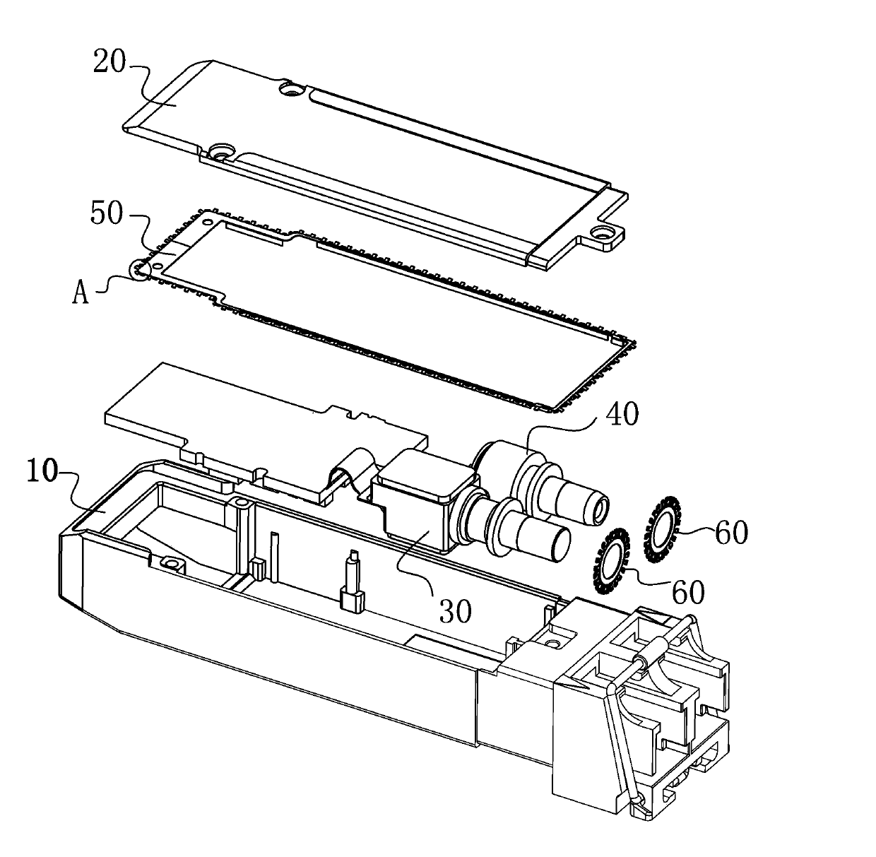
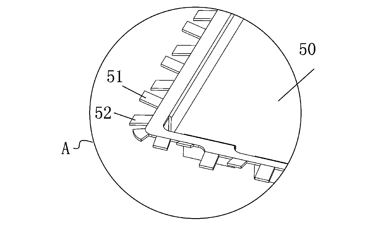
[0022] Such as figure 1 The shown pluggable optical transceiver module includes: a base 10 and an upper cover 20, the base is provided with a light-emitting component 30 and a light-receiving component 40, which are located around the joint surface between the base 10 and the upper cover 20 An electromagnetic shielding gasket 50 is also provided, such as figure 2 shown figure 1 In the partial enlarged view of part A in the middle, a plurality of elastic teeth are arranged on the periphery of the gasket, and a part of the contacts 51 of the elastic teeth are in contact with the periphery of the upper cover 20 to form a conductive connection, and the other part of the contacts 52 are connected to the upper cover 20. The base 10 also forms a conductive connection after the surrounding edges of the base 10 are in contact. The purpose of set...


PUM


Abstract

The invention provides a pluggable optical transceiver module, which comprises a base and an upper cover, wherein a light emitting assembly and a light receiving assembly are arranged in the base; an electromagnetic shielding gasket is also arranged on the periphery between the faying surfaces of the base and the upper cover; the surrounding edge of the gasket is provided with a plurality of elastic tooth sheets; one part of contacts of the elastic tooth sheets is formed into electric conduction connection after making contact with the surrounding edge of the upper cover; the other part of contacts is also formed into conduction connection after making contact with the surrounding edge of the base. Therefore, the contact points of the base and the upper cover are increased, a plurality of electric conduction connection points are formed, and therefore, the electromagnetic shielding effect is improved.

Description

technical field [0001] The invention relates to a pluggable optical transceiver module. Background technique [0002] As the transmission speed of the optical transceiver module increases, an obstacle more and more encountered involves electromagnetic interference or EMI (Electromagnetic Interference). EMI is the electrical noise generated by the components of the optical transceiver module, expressed in the form of electromagnetic waves emitted by the module. [0003] The packaging of the optical transceiver module, especially the packaging of the optical transceiver module working at a high transmission speed, is particularly prone to electromagnetic interference EMI. This phenomenon is undesirable because EMI can interfere with the normal operation of other electronic components. Especially when the generation speed of the optical transceiver module increases, its physical configuration does a poor job in suppressing EMI. Some areas of the optical transceiver module, s...

Claims


Application Information

Patent Timeline
IPC IPC(8): G02B6/42H05K9/00
Inventor 张晓峰何伟强许君
Owner SHENZHEN NEOPHOTONICS TECH
Why Eureka
Eureka Blog
Learn More