
High-performance low-noise aircraft exhaust systems and methods

a low-noise, aircraft-based technology, applied in the direction of airflow influencers, jet flaps, transportation and packaging, etc., can solve the problem that aircraft designs are typically limited to a maximum takeoff weight, and achieve the effect of improving lift performance, reducing noise, and improving high-lift capability

Inactive Publication Date: 2010-06-01
THE BOEING CO
View PDF29 Cites 7 Cited by
  • Summary
  • Abstract
  • Description
  • Claims
  • Application Information

AI Technical Summary

Benefits of technology

The invention provides improved aircraft exhaust systems and methods that can improve lift performance, reduce noise, and allow for larger payloads, smaller engines, and shorter runways. The exhaust system has an exhaust aperture with an aspect ratio of at least five, which helps to conduct the exhaust flow from the propulsion unit to the wing assembly. The integrated propulsion assembly and exhaust system can also reduce emissions and make the aircraft less visible to radar. The technical effects of the invention include improved performance and efficiency of aircraft engines and reduced noise levels.

Problems solved by technology

Aircraft designs are typically limited to a maximum takeoff weight and an associated runway length.

Method used


Image

  • High-performance low-noise aircraft exhaust systems and methods
  • High-performance low-noise aircraft exhaust systems and methods
  • High-performance low-noise aircraft exhaust systems and methods

Examples


embodiment 0

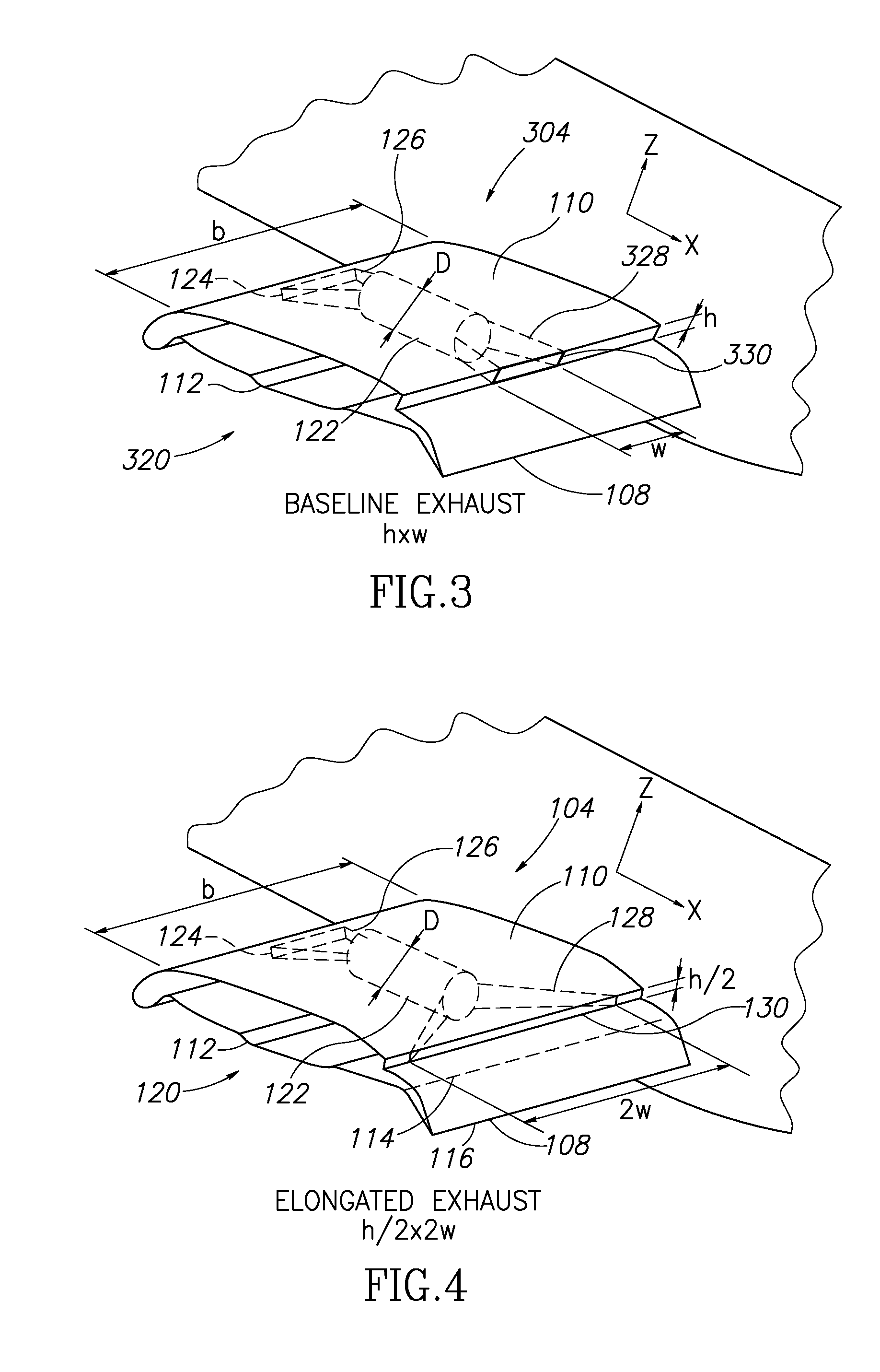
[0036]It will be appreciated that the shape of the exhaust aperture 330 may vary (or may remain constant) depending upon the various operating conditions of the engine 122 throughout the operating regime of the aircraft 100. As shown in FIG. 3, however, at a particular design operating condition of the engine 122 (e.g. maximum power setting, takeoff power setting, etc.), the exhaust aperture 330 has a height h and a width w. More specifically, the exhaust aperture 330 at the design operating condition may provide an exit area (h×w) that is closely comparable to the exit area of prior art exhaust apertures, however, an aspect ratio AR (defined as width over height w / h) of the inventive exhaust aperture 330 is significantly larger than the aspect ratio of prior art exhaust apertures, as described more fully below with respect to FIG. 17. For example, the maximum value of the aspect ratio AR of the exhaust aperture in the prior art is 3.6, while the exhaust aperture 330 of the baseline...

embodiment 00

[0038]More specifically, at the same design operating condition (e.g. maximum power setting, takeoff power setting, etc.), the exhaust aperture 130 may have a reduced height of h / 2 and an elongated width of 2w. Thus, the exhaust aperture 130 provides the same exit area as the baseline exhaust aperture 330, but the aspect ratio AR of the elongated exhaust aperture 130 (4w / h) is approximately 24 (see embodiment 00 of FIG. 17), or approximately 6.7 times greater than the aspect ratio AR of the baseline exhaust aperture 330 (w / h) at the same design operating condition of the engine 122. In alternate embodiments, the aspect ratio AR of exhaust apertures in accordance with the teachings of the present disclosure may be greater than or less than that of the particular configurations shown in FIGS. 3 and 4, as described more fully below with respect to FIG. 17.

[0039]In some embodiments, a set of actuators may be used to move an ensemble of interlocking leaves which collectively form the exh...

second embodiment

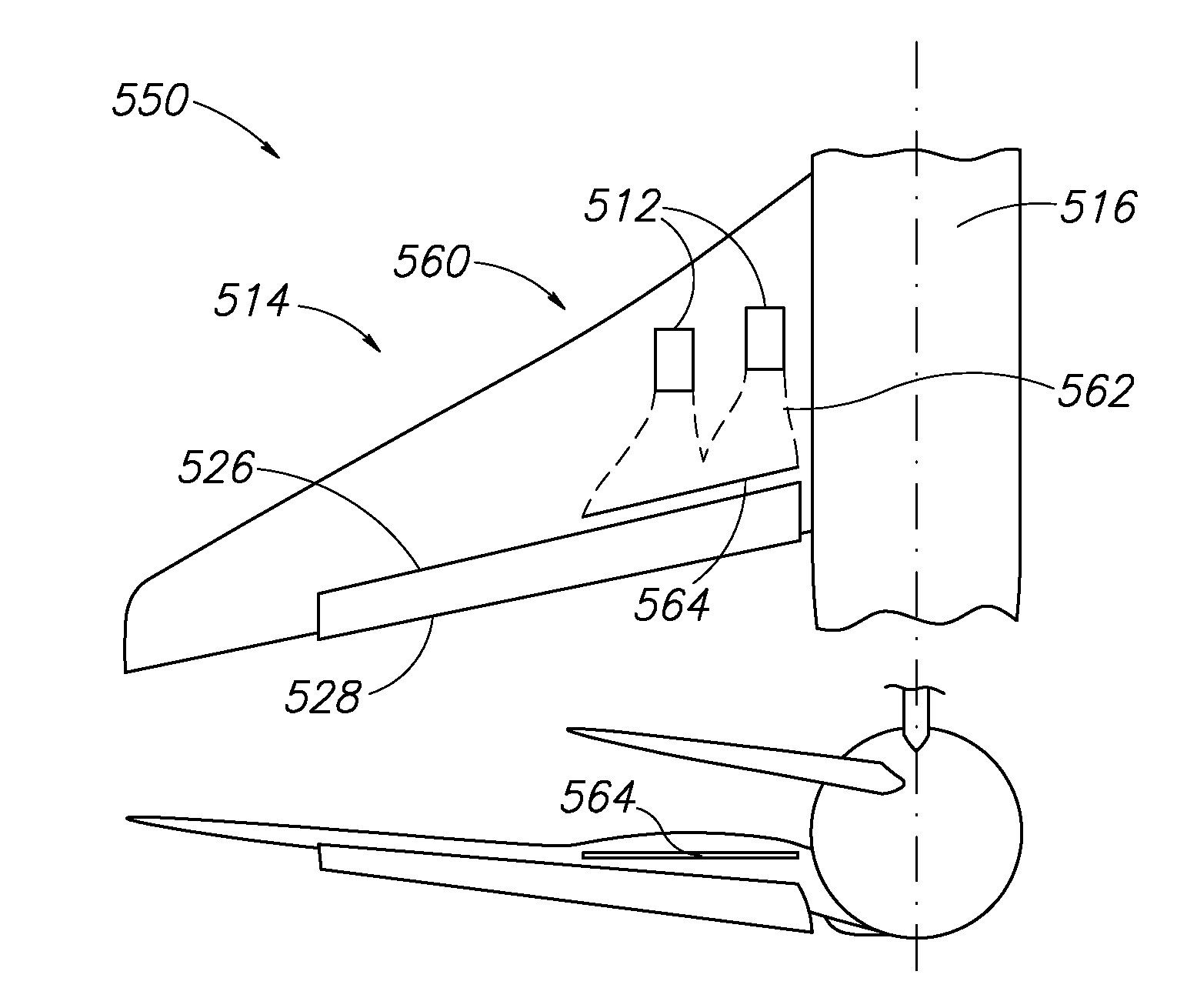
[0059]Similarly, in FIG. 20 the exhaust system 560 corresponding to the table 500 (FIG. 17) includes the engines 512 as in the prior art exhaust system 520. A plurality of exhaust ducts 562 extend rearwardly from the engines 512 to an exhaust aperture 564 having an aspect ratio AR of 33, which is approximately 9 times greater than the aspect ratio AR of the prior art exhaust aperture 524.


PUM


Abstract

Aircraft exhaust systems and methods are disclosed. In one embodiment, an integrated propulsion assembly includes a wing assembly having an upper surface and a lower surface, and a propulsion unit at least partially disposed within the wing assembly. An exhaust system is configured to conduct an exhaust flow emanating from the propulsion unit to an exhaust aperture. The exhaust aperture is positioned proximate a trailing edge of the wing assembly, and has an aspect ratio of at least five. In further embodiments, the wing assembly includes a flap member moveably coupled along a trailing edge portion of the wing assembly, and the exhaust aperture is configured to direct the exhaust flow over at least a portion of the flap member.

Description

FIELD OF THE INVENTION[0001]The field of the present disclosure relates to aircraft exhaust systems, and more specifically, to aircraft exhaust systems and methods that provide improved performance and reduced noise.BACKGROUND OF THE INVENTION[0002]For some types of aircraft, including transport aircraft, high-lift capability is important, particularly for takeoff and landing requirements. Aircraft designs are typically limited to a maximum takeoff weight and an associated runway length. For a given runway length, higher lift levels permit larger aircraft weights. Equivalently, for a given aircraft weight, higher lift allows for a lower stall speed and a shorter runway. From an operational perspective, higher lift translates into access to a larger number of airports. Whether the requirement is for a higher aircraft weight or for shorter runways, superior high-lift capability is a key design objective of the aircraft manufacturers.[0003]It is known that some types of aircraft employ...

Claims


Application Information

Patent Timeline
Patent Type & Authority Patents(United States)
IPC IPC(8): B64C21/04
CPCB64C9/38Y02T50/44Y02T50/40B64D27/12B64D27/18
Inventor SHMILOVICH, ARVINYADLIN, YORAMCLARK, ROGER W.
Owner THE BOEING CO
Learn More