Lift system having individually driven cars and a closed track

Active Publication Date: 2017-10-26
INVENTIO AG
View PDF5 Cites 8 Cited by
  • Summary
  • Abstract
  • Description
  • Claims
  • Application Information

AI Technical Summary

Benefits of technology

[0014]In one exemplary embodiment the gear wheel system has a first gear wheel disk and a second gear wheel disk spaced apart from this, which are arranged on the shaft. The guide disk is arranged between the first and the second gear wheel disk on the shaft. The guide disk , for example, has a guide groove into which the guide edges engage. The functions of guidance and drive are therefore close to one another at the drive unit. This has the advantage that dimensional tolerances, e.g. relating to the distance between guide edges and guide groove need only be maintained over small distances; this is simpler for constricted space than for large distances.
[0015]According to one exemplary embodiment, the gear wheel

Problems solved by technology

The direction reversal by the gear-wheel driven points system of JP 2004

Method used


Image

  • Lift system having individually driven cars and a closed track
  • Lift system having individually driven cars and a closed track
  • Lift system having individually driven cars and a closed track

Examples


Embodiment Construction

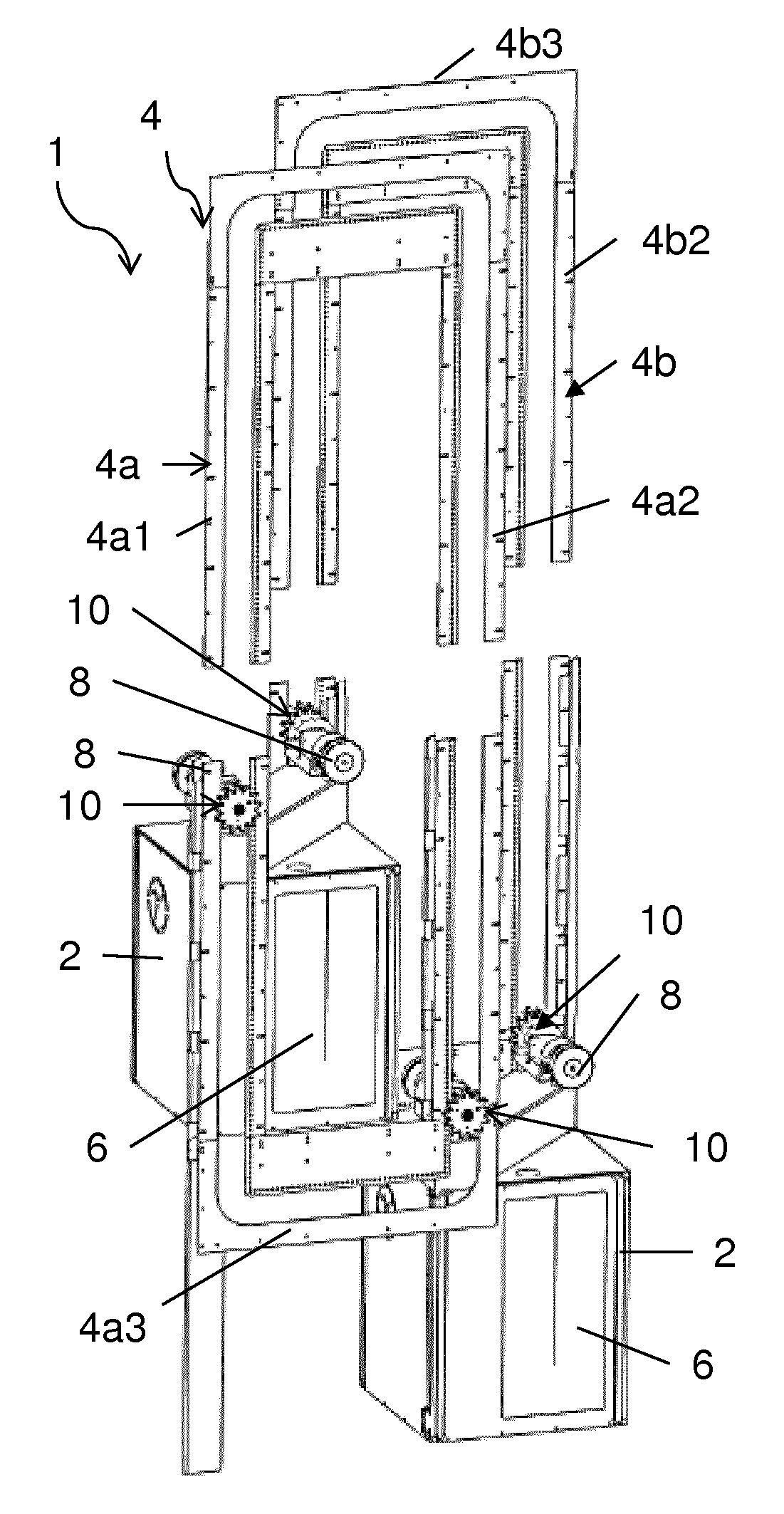
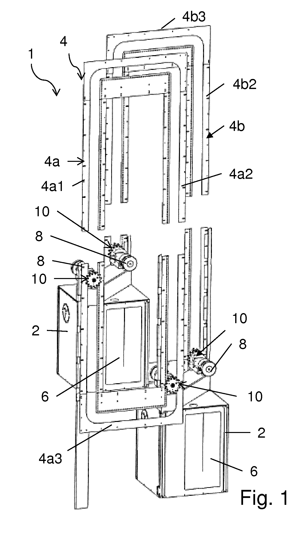
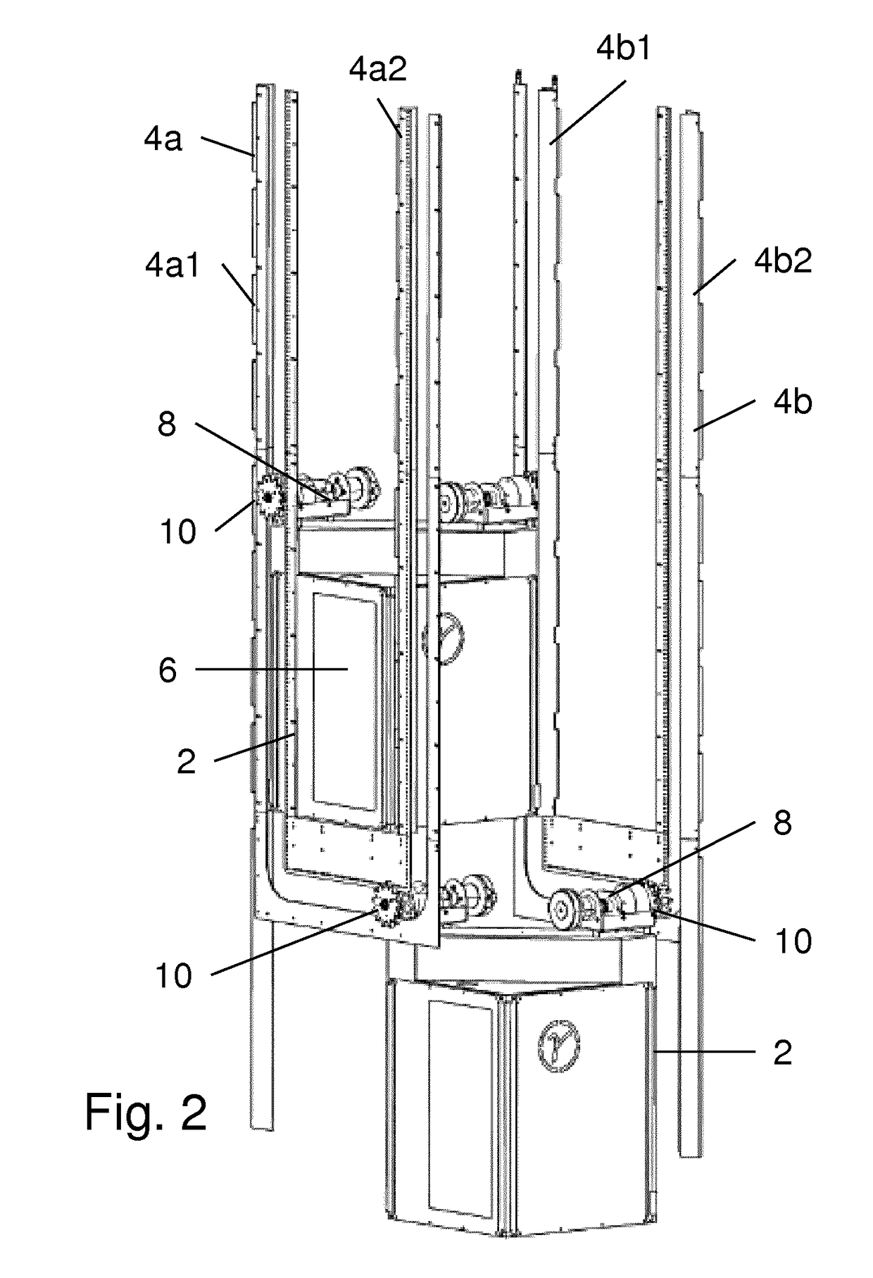
[0038]FIG. 1 shows a perspective and schematic view of an exemplary embodiment of a lift system 1 with a guide system 4 for a plurality of self-driven cars 2 in first positions. FIG. 2 shows an enlarged illustration of a lower region of the lift system 1 from FIG. 1 from a different perspective, where the cars 2 are located in second positions. In both positions the lift cars 2 are located in the lower region of the guide system 4; in FIG. 1 both cars 2 are located on vertical sections of the guide system 4 and in FIG. 2 one of the cars 2 is located on a horizontal section of the guide system 4 whilst the other car 2 is located on a vertical section.

[0039]Such a lift system 1 is usually installed in a shaft inside a multi-storey building. Such a shaft can be variously configured, for example, as a shaft with four walls or as a shaft with less than four walls, for example, as a so-called panorama lift. For better clarity FIG. 1 and FIG. 2 do not show either a shaft or fixing structur...


PUM


Abstract

A lift system for moving a car along a track in a guided manner. The lift system having a guide rail system, a car and a drive unit arranged on the car. The guide rail system forms a closed track along which the car can be moved between floors when in operation. The drive unit has a motor, a gear wheel system connected to the motor by a shaft and a guide disk. The guide rail system has a pinion system and guide edges spaced apart from one another, which cooperate with the guide disk. When in operation, the motor drives the gear wheel system and the gear wheel system acts on the pinion system in order to move the car along the track in a guided manner.

Description

CROSS-REFERENCE TO RELATED APPLICATION[0001]This application is the national phase application under 35 U.S.C. §371 claiming the benefit of priority based on International patent application Ser. No. PCT / EP2015 / 072483, filed on Sep. 29, 2015, which claims the benefit of priority based on European patent application Ser. No. 14187115.2, filed on Sep. 30, 2014. The contents of each of these applications are herein incorporated by reference.FIELD OF THE INVENTION[0002]The technology described here relates in general to lift systems having a plurality of cars in a shaft. The technology relates in particular to those lift systems in which the cars can be moved individually on a closed rail track. Various exemplary embodiments of the technology relate in particular to configurations of the rail track and a drive unit.BACKGROUND[0003]In known lift systems (e.g. traction lifts or hydraulic lifts), a car moves along a linear track in order to transport a passenger from an entry floor to an e...

Claims


Application Information

Patent Timeline
IPC IPC(8): B66B9/02B66B1/24B66B1/34B66B9/00
CPCB66B9/022B66B1/3461B66B9/003B66B1/2433B66B9/10
Inventor FINSCHI, LUKASTROESCHFRIEDLI, PAULSCHUSTER, KILIANVONAESCH, JONAS
Owner INVENTIO AG
Why Eureka
Try Eureka