Method for forming optical aperture, near-field optical head, method for fabricating near-field optical head, and information recording/reading apparatus

a technology of optical aperture and fabrication method, which is applied in the field of forming optical aperture, can solve the problems of a large moving amount of mechanical translation platform, difficult to control and form the aperture, and difficult to achieve the effect of forming an optical aperture easily and economically

Active Publication Date: 2006-04-25
SEIKO INSTR INC
View PDF12 Cites 29 Cited by
  • Summary
  • Abstract
  • Description
  • Claims
  • Application Information

AI Technical Summary

Benefits of technology

[0010]The present invention has been achieved to overcome the foregoing problems in the conventional art. It is an object of the invention to provide a method for forming an optical aperture easily and economically.

Problems solved by technology

However, it is only hoped that these techniques will result in the improvement to the extent of a few times current recording density due to a problem of the diffraction limit of light.
Furthermore, it takes much time to adjust a waveguide rod to vertically abut on the flat plate.
Moreover, in addition to the piezoelectric actuator having a small moving amount, a mechanical translation platform having a large moving amount is needed.
Besides, when the pressing amount is controlled by using the piezoelectric actuator having a small moving resolution, a control unit is required and it takes a few minutes to control and form the aperture.
In addition, a problem has arisen that costs for aperture formation are increased.
However, since the aperture is formed by using the FIB, the time required to form one aperture is as long as ten minutes.
Thus, a problem has arisen that fabrication costs for aperture fabrication are increased.

Method used


Image

  • Method for forming optical aperture, near-field optical head, method for fabricating near-field optical head, and information recording/reading apparatus
  • Method for forming optical aperture, near-field optical head, method for fabricating near-field optical head, and information recording/reading apparatus
  • Method for forming optical aperture, near-field optical head, method for fabricating near-field optical head, and information recording/reading apparatus

Examples


embodiment 1

(Embodiment 1)

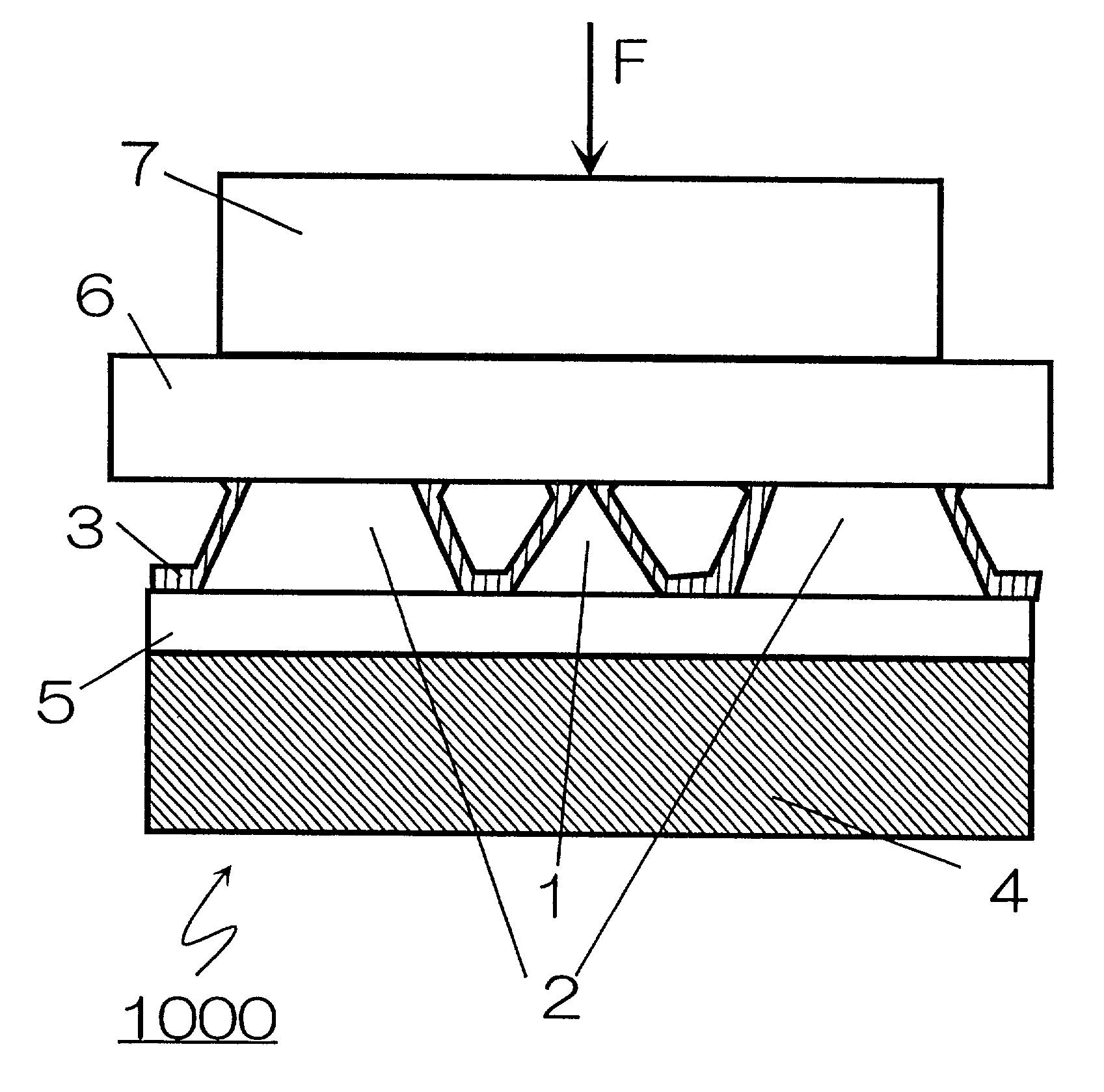
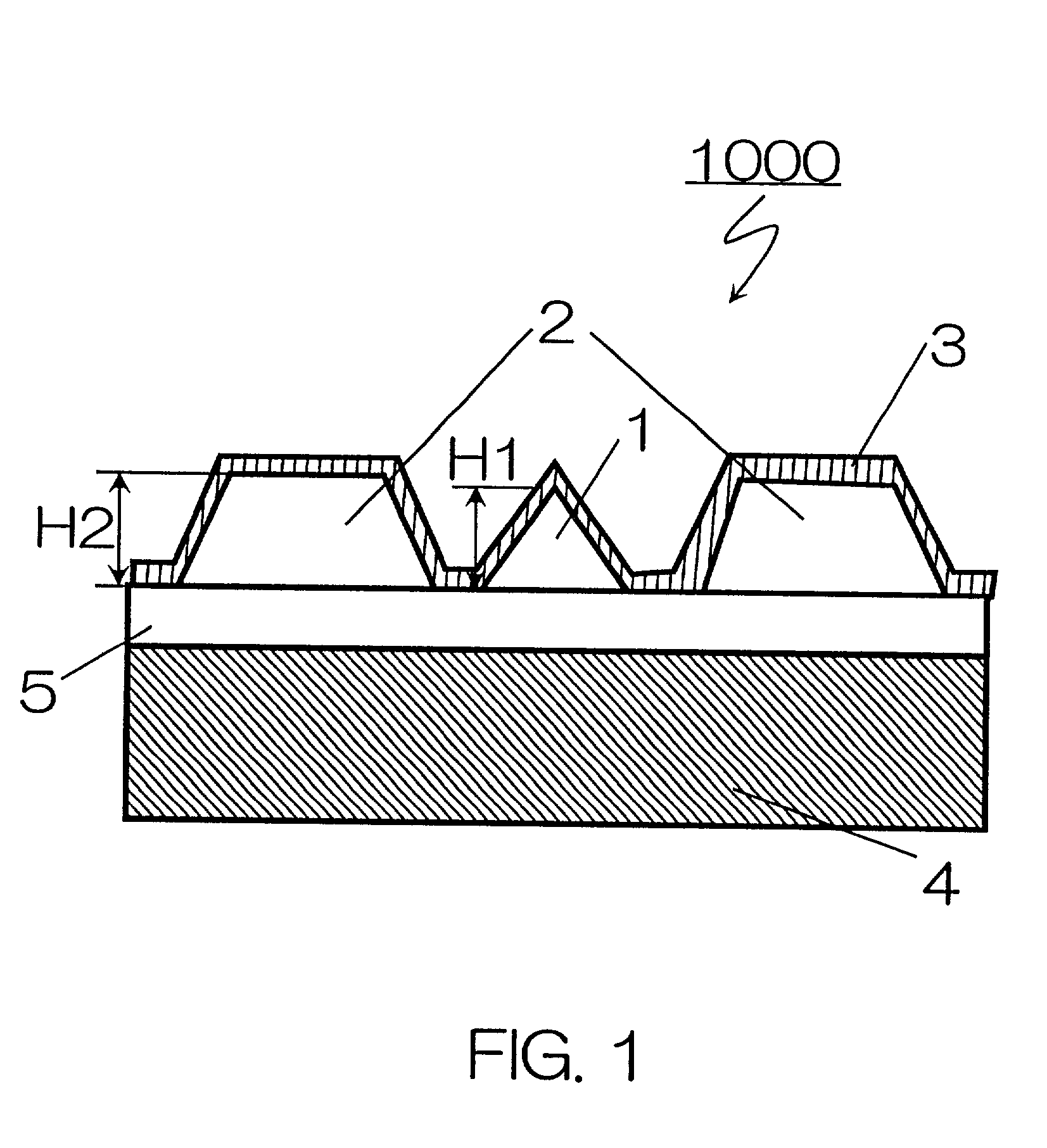
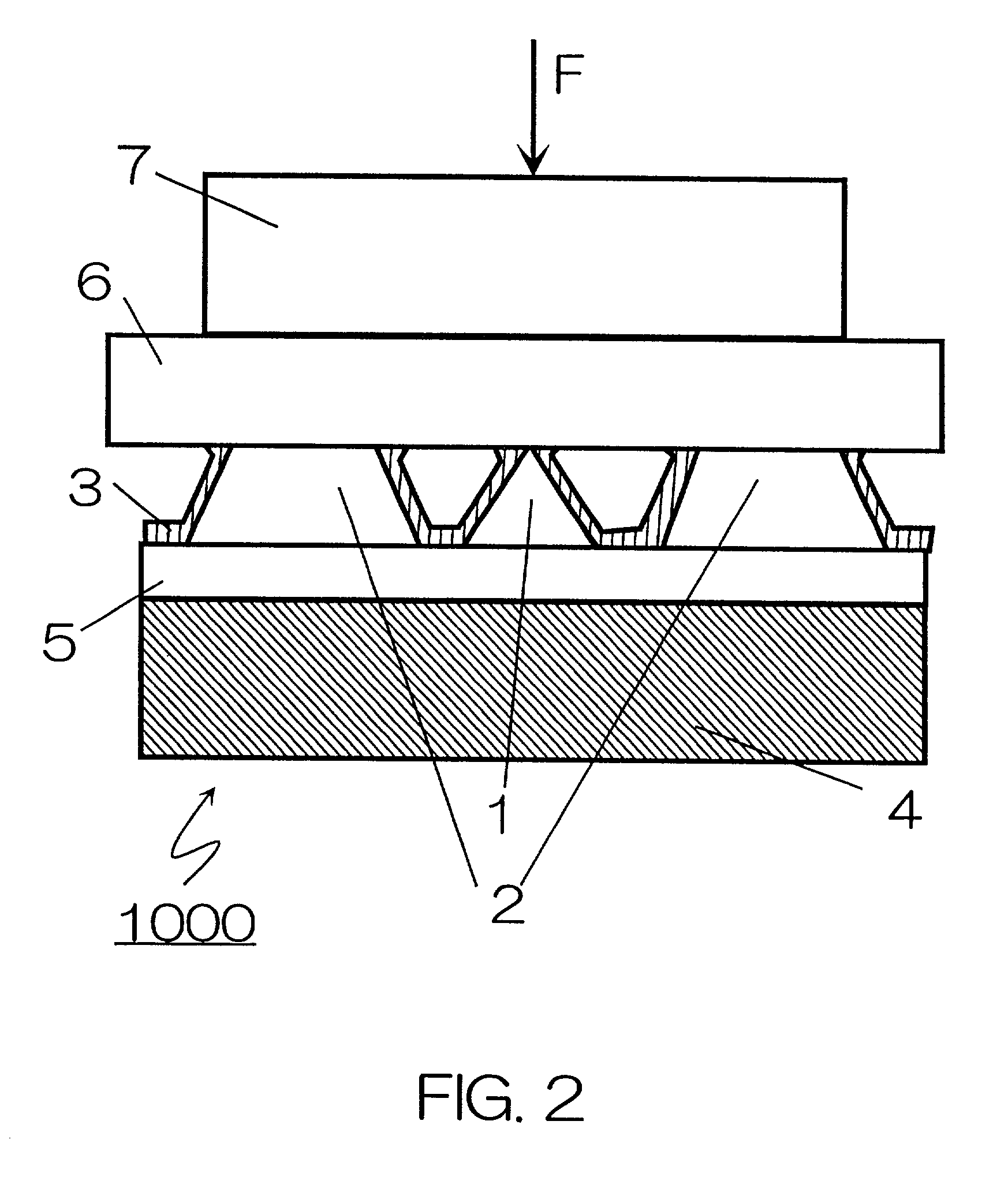
[0062]The method for forming the aperture of the invention will be described referring to FIGS. 1 to 3. FIG. 1 is a cross-sectional diagram showing a schematic configuration of an object or work 1000. As shown in the drawing, the work 1000 comprises a transparent layer 5 formed on a substrate 4, a tip of conical or pyramidal shape 1 and a ridge-shaped stopper 2 formed on the transparent layer 5, and an opaque film 3 formed on the tip 1, the stopper 2 and the transparent layer 5. Additionally, the transparent layer 5 is not necessarily needed here; in that case, the opaque film 3 is formed on the tip 1, the stopper 2 and the substrate 4. Furthermore, the opaque film 3 may be deposited only on the tip 1.

[0063]A height H1 of the tip 2 is equal to or under a few millimeters; a height H2 of the stopper 2 is equal to or under a few millimeters. The distance between the tip 1 and the stopper 2 is equal to or under a few millimeters. Besides, a thickness of the opaque film 3 i...

embodiment 2

(Embodiment 2)

[0081]Next, a near field optical head in an embodiment 2 of the invention will be described. FIG. 8 depicts a schematic diagram illustrating a near field optical head for a high density memory having the aperture produced by the method described in the embodiment 1. Besides, the details of the periphery of the aperture are not illustrated here. Referring to FIG. 8, a method for reproduction (reading information) and recording (writing information) will be described in an information recording / reading apparatus using the near field optical head in the embodiment 2.

[0082]FIG. 8 depicts a manner of reproduction using a so-called illumination mode. Here, a light entered to a near field optical head 11 is entered from the direction approximately parallel to a recording medium. Of course, the light may be entered from the direction approximately orthogonal or oblique to the recording medium as well. A waveguide 13 is disposed inside the near field optical head 11. The light ...

embodiment 3

(Embodiment 3)

[0107]FIG. 16 depicts a schematic view illustrating a near field optical head in an embodiment 3. FIG. 16 depicts air-bearing surfaces 27 and a tip 28 being top. In a near field optical head 50 in the embodiment 3, a groove 29 is formed on a part of each of the air-bearing surfaces 27 and the tip 28 is formed in a part of the groove 29. The stoppers shown in the embodiment 2 are not formed. In FIG. 16, the circular grooves 29 are formed but they may be triangular, rectangular or polygonal not limiting to circle. However, the tip 28 is always placed in the center of the groove. Additionally, two grooves 29 are depicted in FIG. 16 but one or multiple grooves may be formed not limiting to two. However, in order to keep the lateral balance of the lift force that the air-bearing surfaces 27 receive, the grooves 29 are desired to be formed at the same lateral positions on the two air-bearing surfaces 27 as shown in FIG. 16. The positions of the grooves 29 are determined acco...


PUM

PropertyMeasurementUnit
heights H1aaaaaaaaaa
heightsaaaaaaaaaa

Abstract

In a method of producing an optical aperture, there is provided an object having a substrate, at least one conical- or pyramidal-shaped tip disposed on the substrate, at least one stopper disposed on the substrate in the vicinity of the tip and having a height substantially equal to a height of the tip, and an opaque film disposed at least on the tip. A pressing body is disposed relative to the object so that a surface of the pressing body is disposed over the tip and at least a portion of the stopper. The pressing body is then displaced to bring the surface of the pressing body into contact with the object so that a force component is directed to a front end of the tip to form an optical aperture at the front end of the tip.

Description

BACKGROUND OF THE INVENTION[0001]1. Field of the Invention[0002]The present invention relates to a near-field optical head for recording / reading information on a recording medium by utilizing the interaction of a near field light, and to a method for fabricating the same.[0003]2. Background Information[0004]An information recording / reading apparatus using lights has been evolving into the realization of large capacity and downsizing. On that account, the realization of a high density recording bit is demanded. As measures for that, studies using a blue-violet semiconductor laser or an SIL (Solid Immersion Lens) have been conducted. However, it is only hoped that these techniques will result in the improvement to the extent of a few times current recording density due to a problem of the diffraction limit of light. As contrast to this, a method for recording / reading information utilizing a near field light is expected as a technique of handling optical information in microregions exc...

Claims


Application Information

Patent Timeline
Patent Type & Authority Patents(United States)
IPC IPC(8): B21D28/00G11B9/00B81B1/00G01Q60/22G01Q80/00G11B7/09G11B7/12G11B7/135G11B7/22G11B11/105
CPCG11B7/0937G11B7/124G11B7/1387G11B7/22G11B7/1203B82Y10/00B82Y20/00G01Q80/00G11B11/1058G11B7/122
Inventor NIWA, TAKASHIKATO, KENJIMITSUOKA, YASUYUKIOUMI, MANABUKASAMA, NOBUYUKIICHIHARA, SUSUMUMAEDA, HIDETAKASHINOHARA, YOKO
Owner SEIKO INSTR INC
Why Eureka
Try Eureka