Optical shutter dimming helmet visor

a technology of optical shutter and visor, which is applied in the field of optical shutter dimming helmet visor, can solve the problems of plastic material, difficult to ensure the constant distance of the optical shutter, and the difficulty of making the optical shutter work on a curved panel, etc., and achieves the effect of convenient transportation, low power consumption and better satisfying user preferences

Inactive Publication Date: 2012-11-22
SAADAT HAMID
View PDF10 Cites 28 Cited by
  • Summary
  • Abstract
  • Description
  • Claims
  • Application Information

AI Technical Summary

Benefits of technology

[0012]Optical shutter technology provides several advantages. Among these are near instantaneous or immediate switching from a clear state to a dark state. Optical shutters can be incorporated into curved panels and flexible panels for a vast array of applications including helmets, visors, cockpit windows, car windows, boat windshields, food storage containers, shower walls, and the like. Photodiode controlled optical shutters read the intensity of sunlight and command the battery to apply a voltage which causes liquid crystals to adjust transmission accordingly. In addition to automatic adjustment manual adjustment is provided for safety and fine tuning to better satisfy user preferences. Advantageously, optical shutters are thin, lightweight, and use little power so they can be easily transported and do not prohibitively influence manufacturing and shipping costs.

Problems solved by technology

While optical shutter technology has been proven to work for flat surfaces (e.g. arc welding helmet shields), it is very challenging to make it work on a curved, plastic material as the two plastic substrates that must be brought together (through fastening, glue, other adhesives, etc.) will be stretched a bit differently when curved.
Making a twisted nematic (TN) liquid crystal (LC) shutter on a curved plastic operable presents a previously unaddressed challenge.
Part of this challenge is that the distance between the two glass or plastic substrates of the shutter (see FIG. 2 herein) must be kept constant and when something flexible is bent it is difficult to ensure this distance is kept constant.
The other technical difficulty is in the manufacture.
There are no high volume manufacturing lines making plastic LC shutters or displays, and this creates challenges in terms of equipment, raw materials sourcing, and lowering the cost of the process.

Method used


Image

  • Optical shutter dimming helmet visor
  • Optical shutter dimming helmet visor
  • Optical shutter dimming helmet visor

Examples


Embodiment Construction

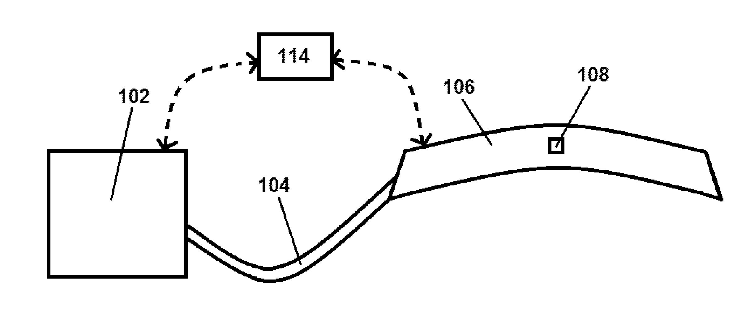
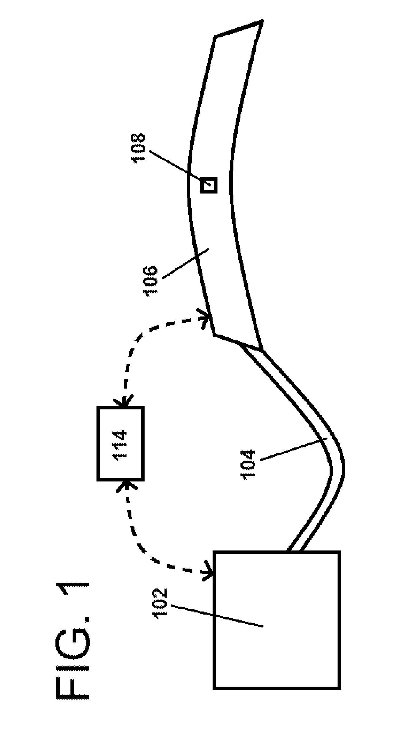
[0025]Briefly and in general terms, the several embodiments of the present invention integrate optical shutter technology in a curved or flexible surface or panel. One preferred application for such technology is use as a visor in a helmet for motorcyclists.

[0026]The optical shutter may consist of only a single pixel or may include multiple pixels. In one embodiment, the physical dimensions of the optical shutter are 177.8 mm (length)×25.4 mm (width)×0.25 mm (thickness) or 7 inches (length)×1 inch (width)×0.0984 inches (thickness). The radius of curvature of the optical shutter may be between 80-160 mm, 90-150 mm, 100-140 mm, 110-130 mm, or 115-125 mm. In one embodiment, the radius of curvature is 121 mm. A suitable radius of curvature for the optical shutter depends on the bend radius of the helmet shield with which it will be used.

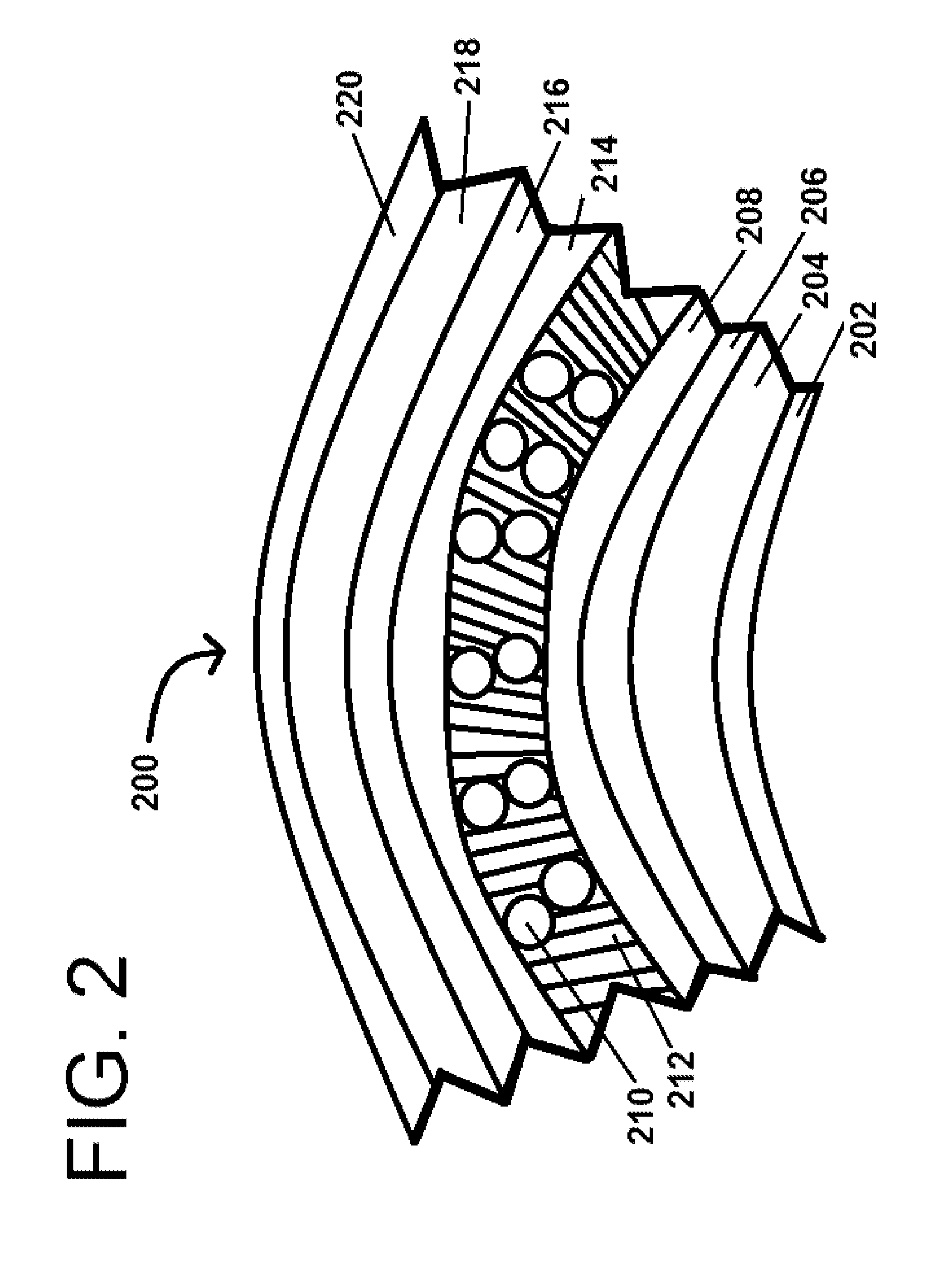
[0027]The optical shutter panel may initially be flat yet formed within a flexible material that permits it to be curved for affixing to a final object ...


PUM

PropertyMeasurementUnit
lengthaaaaaaaaaa
lengthaaaaaaaaaa
timeaaaaaaaaaa

Abstract

Provided is a dimming helmet visor incorporating optical shutter technology therein for instantaneous conversion from a clear state to a dark state and vice versa. These visors find utility in helmets for anyone in changing lighting conditions outdoors, especially motorcyclists. The visor's optical shutter display is connected to a photodiode and a battery with both automatic and manual adjustment functionalities. A manual on/off switch is provided for power management. The photodiode responds to light intensity above a certain threshold and switches from a clear state to dark state in a matter of milliseconds once this threshold is reached.

Description

CROSS-REFERENCES TO RELATED APPLICATIONS[0001]This application claims priority from co-pending U.S. Provisional Application Ser. No. 61 / 487,144 filed May 17, 2011 which is herein incorporated by reference in its entirety.BACKGROUND[0002]1. Field of the Invention[0003]The present invention relates to new uses and applications for optical shutter technology. More specifically, the present invention applies optical shutter technology in a curved panel. Most specifically, the present invention is directed to use of optical shutters in curved panels as helmet visors to improve visibility by reducing glare and blinding sunlight for motorcyclists.[0004]2. Description of the Related Art[0005]Traditionally, to reduce the impact and brightness of sunlight motorcyclists could wear sunglasses or have tinted glass panels and visors integrated with their helmets. Disadvantages of fixed tint mediums are that they do not address a riding environment exhibiting variable and erratic fluctuations in b...

Claims


Application Information

Patent Timeline
Patent Type & Authority Applications(United States)
IPC IPC(8): G01J1/44G02F1/01
CPCG01J1/18G02F1/13306G02F2201/58G02F2001/13312G02F1/133305G02F1/13312
Inventor SAADAT, HAMID
Owner SAADAT HAMID
Why Eureka
Try Eureka