Lifting apparatus and method for oil field related services

Inactive Publication Date: 2005-01-11
WARRIOR ENERGY SERVICES
View PDF12 Cites 10 Cited by
  • Summary
  • Abstract
  • Description
  • Claims
  • Application Information

AI Technical Summary

Benefits of technology

Apparatus and method are disclosed for increasing the lifting capacity of apparatus used for lifting blowout preventers below the floor of a drilling rig by employing four simultaneously operated winches to perf

Problems solved by technology

If subsurface fluids flow to the surface

Method used


Image

  • Lifting apparatus and method for oil field related services
  • Lifting apparatus and method for oil field related services
  • Lifting apparatus and method for oil field related services

Examples


Embodiment Construction

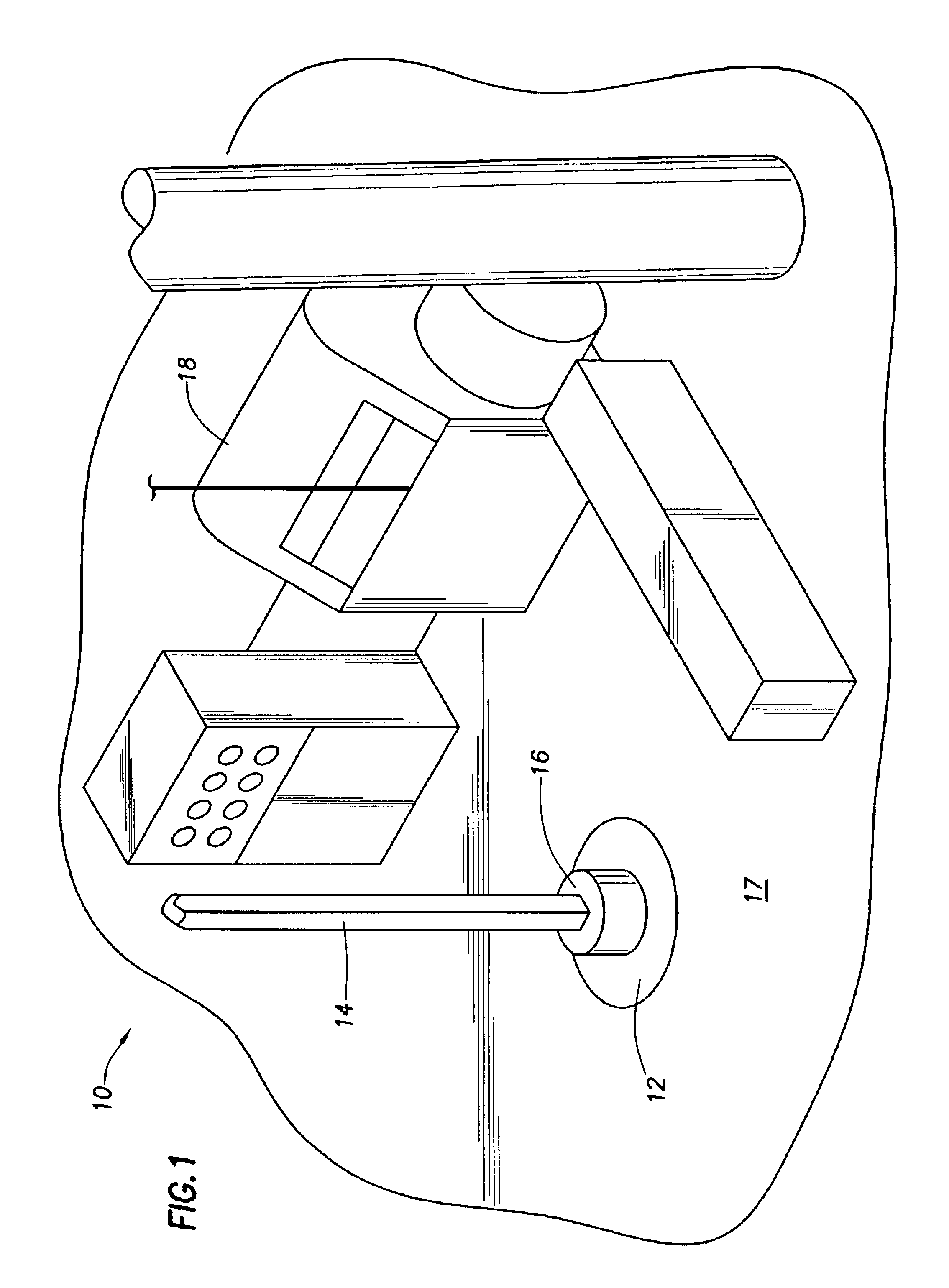
Referring to FIG. 1, a view of a floor of a typical drilling rig is shown. Rotary table 12 is turned by a drive mechanism (not shown) below rig floor 17. Kelly joint 14 passes through master bushing 16 and is connected to drill pipe in the hole being drilled. Drilling line or cable passing over sheaves in a mast (not shown) is operated by a winch in draw works 18 and is used for supporting the drill string and lowering it as hole is drilled. The drill string passes through a blowout preventer stack (not shown) that is beneath rotary table 12.

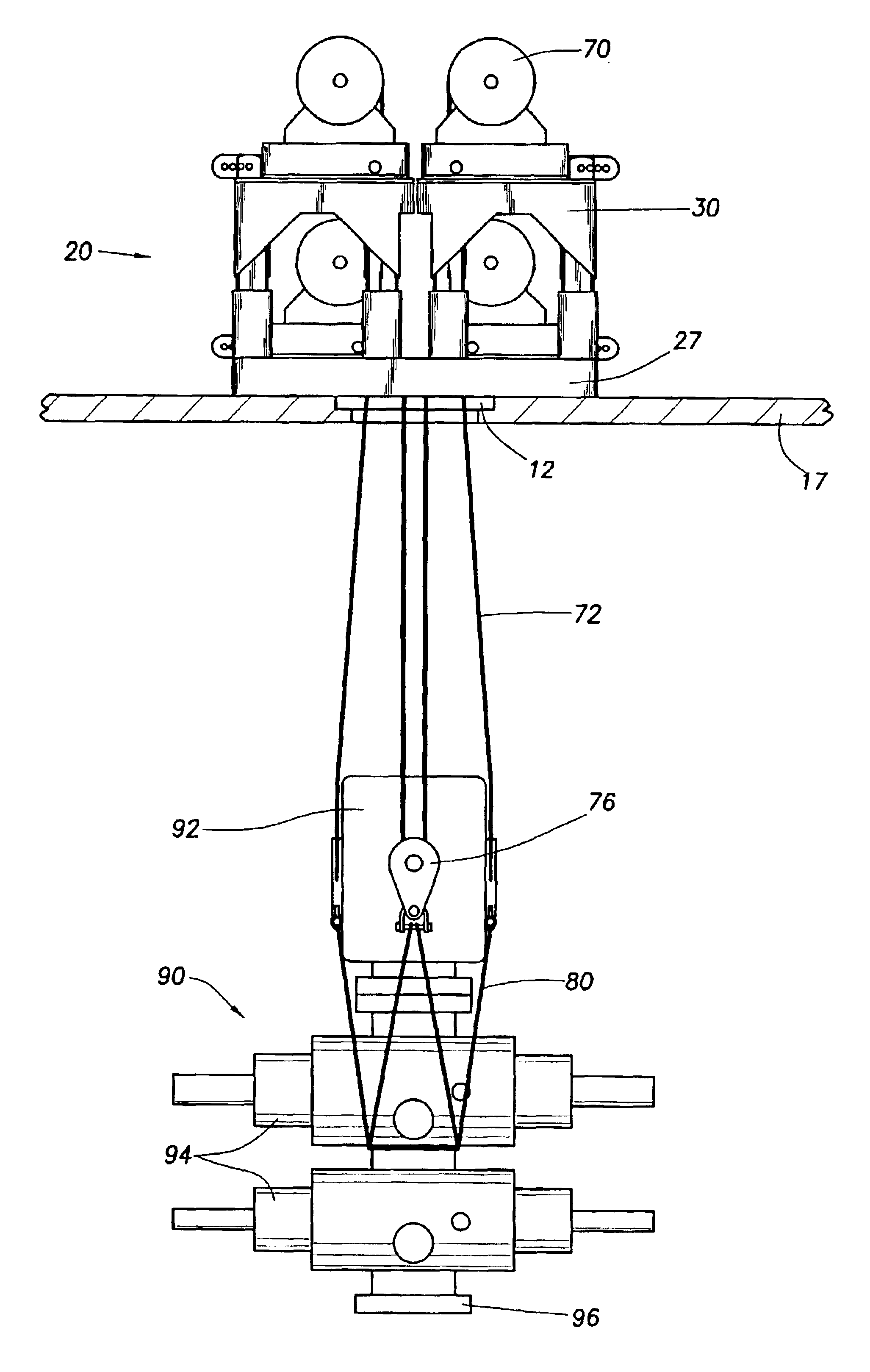
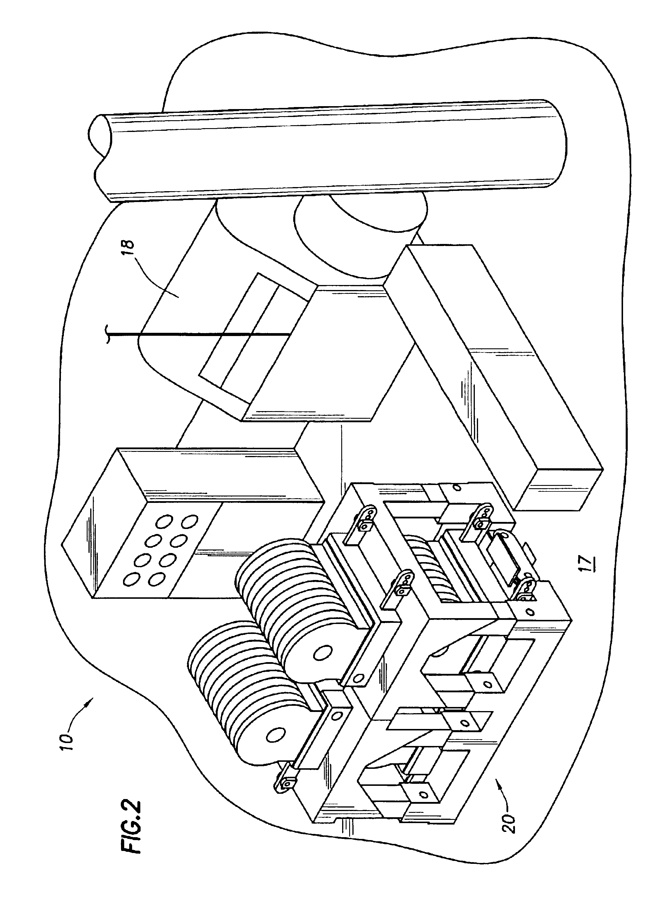
When a blowout preventer or other heavy equipment is to be lifted under the drilling floor, kelly joint 14 and the connected drill string are removed from the well. Master bushing 16 can then be removed, leaving a flat surface of rotary table 12 at about the level of rig floor 17. Horizontal room on the floor is limited by equipment such as shown in FIG. 1. Referring to FIG. 2, lift system 20, disclosed herein, can then be placed over the rotary...


PUM


Abstract

Apparatus and method are provided for lifting heavy loads beneath the floor of a drilling rig or a platform. A base skid supports tables to which winch bases are attached. Winches, usually four in number, are placed on the winch bases and the cables of the winches are placed through sheaves and attached to a double line bar. Sheaves are attached to a load, such as a blowout preventer. Cradle lines may support a blowout preventer. Load cells may be used with the winch cables.

Description

BACKGROUND OF THE INVENTION1. Field of the InventionThis invention relates to drilling and servicing of wells. More particularly, improved apparatus and method for lifting blowout preventers or other heavy loads below the floor of a drilling rig or the main deck of a platform are provided.2. Description of Related ArtBlowout preventers (BOPS) are used on drilling rigs to prevent continued influx of subsurface fluids into a drilling well, displacing the drilling fluid from the wellbore. As drilling fluid is displaced from the well at the surface of the earth, the hydrostatic pressure available to control influx of subsurface fluids is decreased, allowing influx of subsurface fluids at an even higher rate. If subsurface fluids flow to the surface of the earth, a “blowout” has occurred. Such occurrences are normally avoided by closing one or more of the BOPs in a BOP “stack” upon detection of significant flow of drilling fluid at the surface of a wellbore and then taking other steps to...

Claims


Application Information

Patent Timeline
IPC IPC(8): E21B19/00
CPCE21B19/008
Inventor SHIYOU, AL JOSEPH
Owner WARRIOR ENERGY SERVICES
Why Eureka
Try Eureka