[0007]An object of the present invention is to wholly or partly overcome the above disadvantages and drawbacks of the prior art. More specifically, it is an object to provide a simple overhead travelling crane which easily may be incorporated in existing and new nacelles.
[0008]It is also an object of the present invention to provide an overhead travelling crane which has a simple construction and is reliable during use and while exerted with loads.
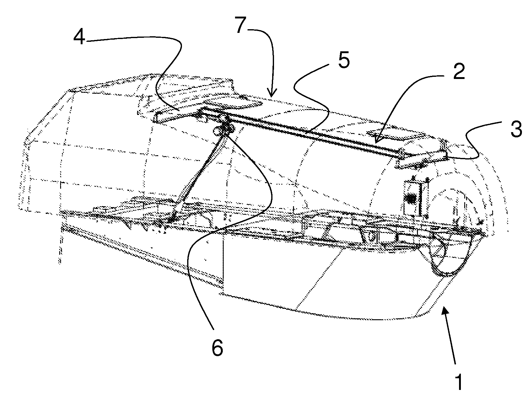
[0009]Another object of the present invention is to provide an overhead travelling crane which is flexible and which can cover substantially the entire area of the nacelle.
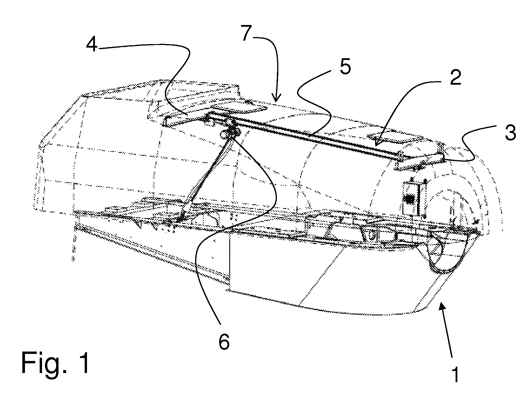
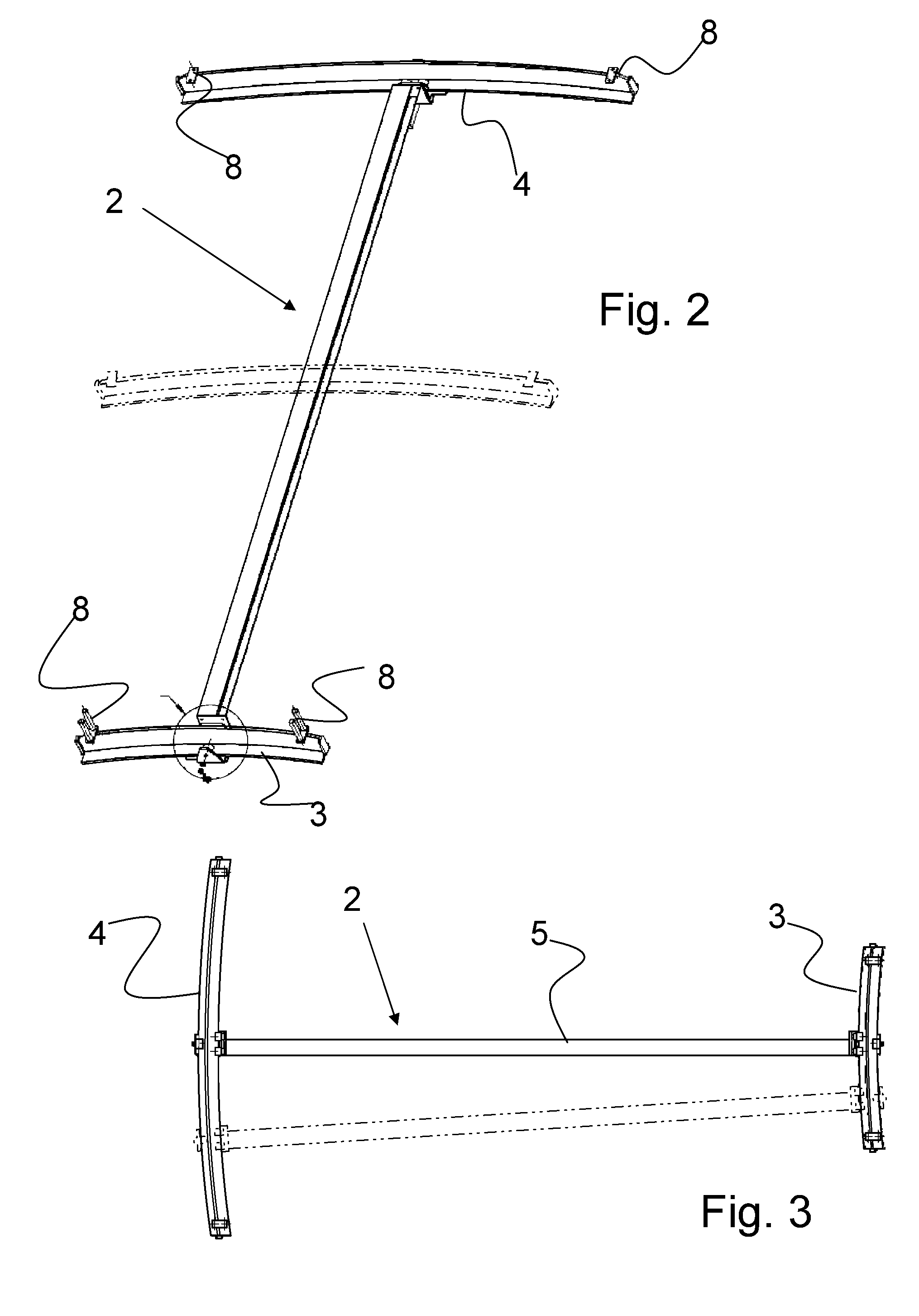
[0011]The above objects, together with numerous other objects, advantages and features, which will become evident from the below description, are accomplished by a solution in accordance with the present invention by said travelling crane comprising at least a first suspension beam, a second suspension beam, said suspension beams being arranged with a space between them, a cross beam, said cross beam being movably connected to said first and second suspension beams so that the cross beam can be moved along the suspension beams, and at least one lifting device, said lifting device being movably connected to the cross beam, wherein said first and second suspension beams are parts of concentric circles, said concentric circles sharing the same centre and having different radii.
[0012]The matter is that the parts of concentric circles share the same centre and have different radii. Hereby, at anytime during its movement along the beams, the cross beam will be perpendicular to both of the suspension beams, whereby the tendency of the cross beam to tilt and thereby to exert unintended forces to the movable connections between the suspension beams and the cross beam substantially is avoided. Also, the use of displaceable arrangements for the cross beam as well as the use of rotatable, movable couplings between the suspension beams and the cross beam are avoided. Furthermore, it is obtained that the travelling crane substantially may cover the entire area of the nacelle which provides flexible internal crane solution to the nacelle, which at the same time is reliable during use.
[0020]In an aspect of the present invention, a third suspension beam (shown in phantom in FIG. 2) may be arranged at a distance from the first suspension beam in the space between the first and the second suspension beams, the cross beam being movably connected to said third suspension beam. Hereby it is obtained that the cross beam is additionally suspended as well as supported, whereby the lifting capacity of the travelling crane may be increased. Within the wind turbine technology, there is a tendency that the capacities as well as the sizes of the wind turbines increase and as the wind turbines are becoming larger, the sizes as well as weights of the parts placed in the nacelle also increase, whereby the third suspension beam may facilitate lifting of the parts of the nacelle. Advantageously, the third suspension beam is as well a part of the concentric circles as the suspension beams, sharing the same centre but having a different radius in relation to the radii of the first and second suspension beams. The placement of the third suspension beam and the distance from the first suspension beam, and thereby the additional support of the crane, may be chosen in view of the load distribution in the nacelle.

