Methods and systems for monitoring glass and/or foam density as a function of vertical position within a vessel

a technology of vertical position and glass, which is applied in the field of submerged combustion furnaces, can solve the problems of high turbulence, rapid melting of glass batches, and difficult to ascertain the local and bulk distribution (size and/or location) of bubbles within molten glass

Active Publication Date: 2014-07-31
JOHNS MANVILLE CORP
View PDF14 Cites 21 Cited by
  • Summary
  • Abstract
  • Description
  • Claims
  • Application Information

AI Technical Summary

Benefits of technology

[0017]one or more EM wave-based sensors a configured and positioned to determine density of the molten foamed glass in either the melter, the downstream apparatus, or both as a function of distance from a structural feature of the melter or downstream apparatus, or

Problems solved by technology

The introduction of high flow rates of products of combustion of the oxidant and fuel into the molten glass, and the expansion of the gases cause rapid melting of the glass batch and much turbulence, and possibly foaming.
When molten glass contains a large amount of bubbles, or has a layer of foam floating on top, or both of these conditions exist, it can be extremely difficult to ascertain the local and bulk distribution (size and/or location) of bubbles within the molten glass, and therefore the local and bulk glass densi

Method used


Image

  • Methods and systems for monitoring glass and/or foam density as a function of vertical position within a vessel
  • Methods and systems for monitoring glass and/or foam density as a function of vertical position within a vessel
  • Methods and systems for monitoring glass and/or foam density as a function of vertical position within a vessel

Examples


embodiment 100

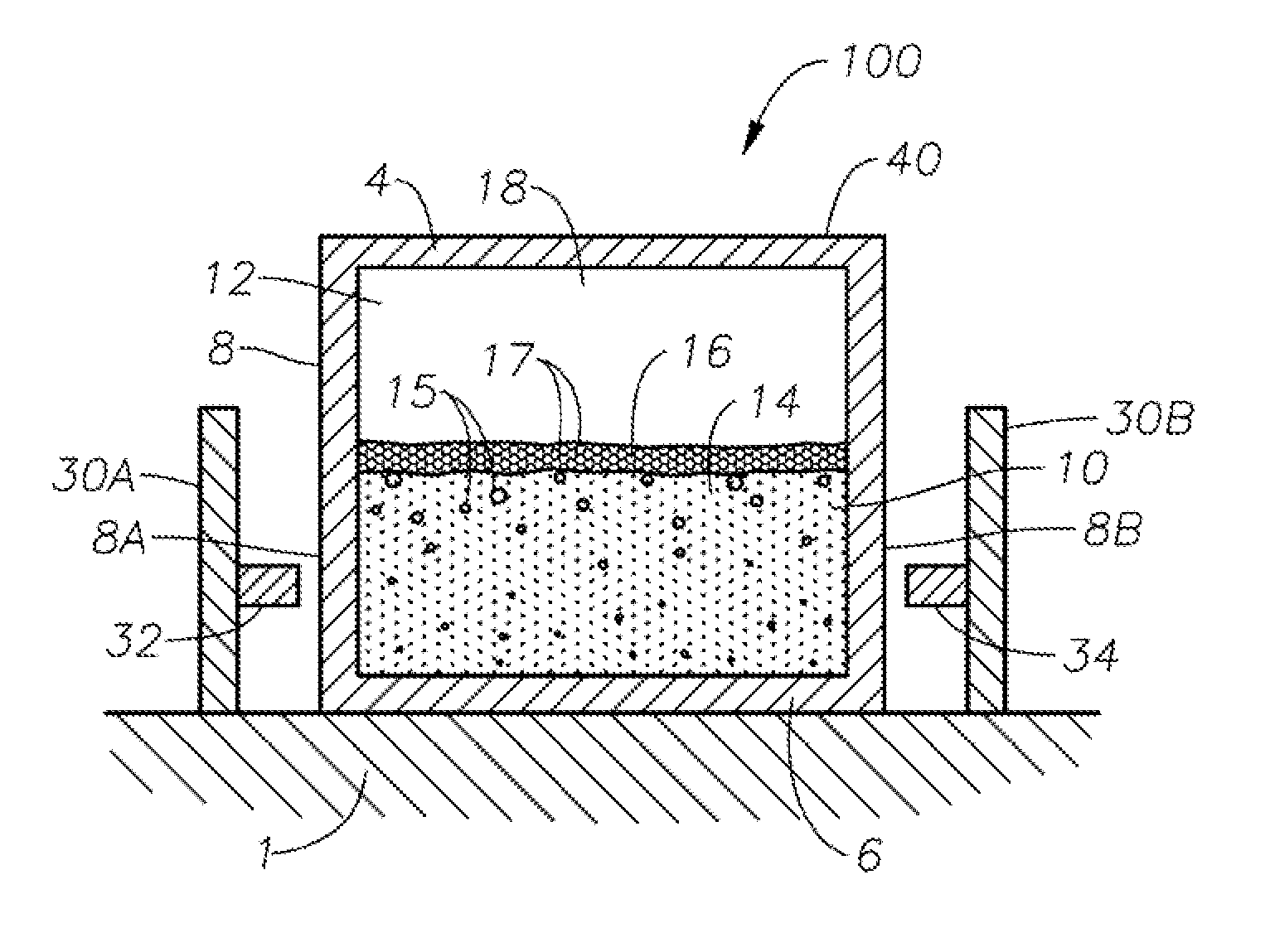
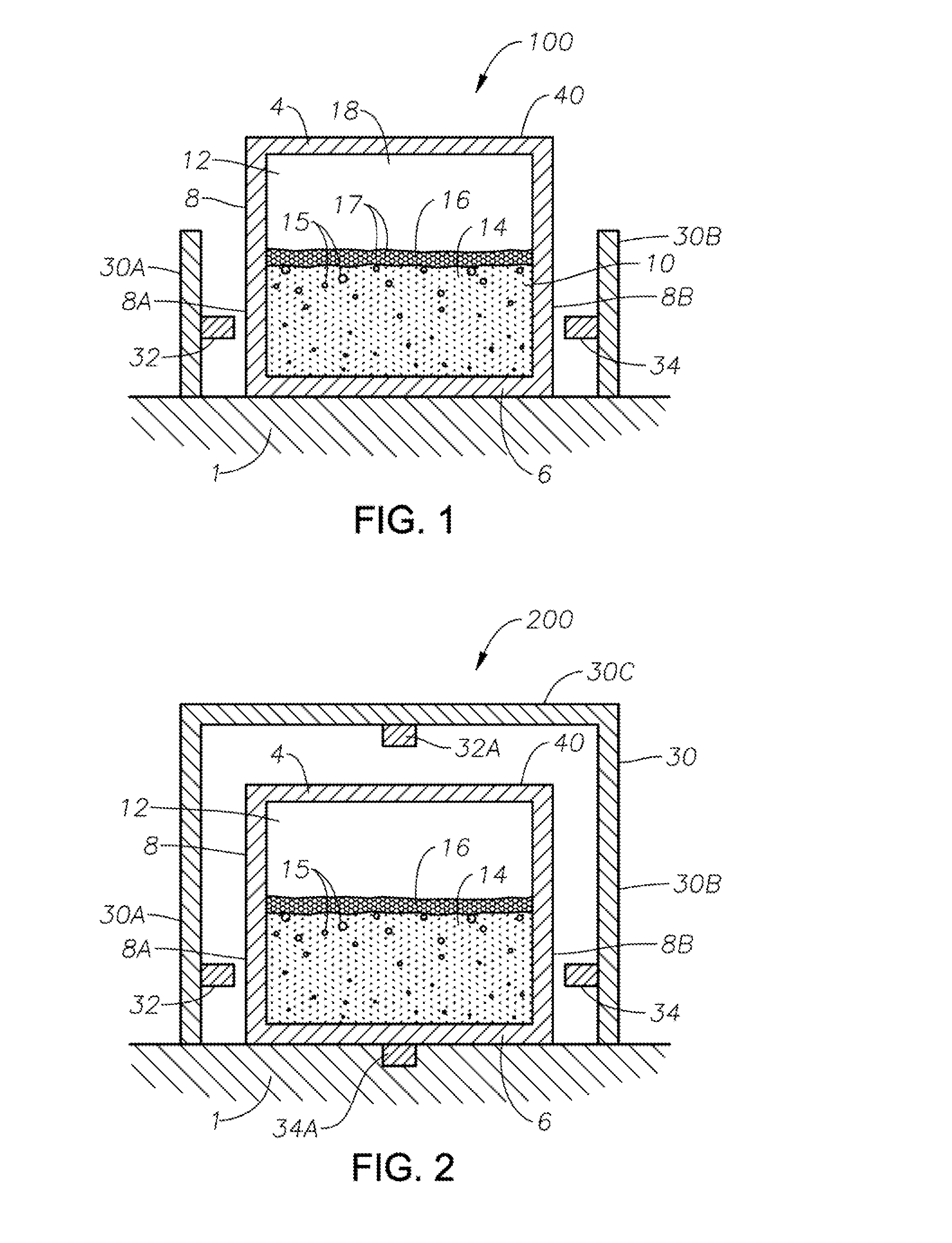
[0062]Referring again to FIG. 1, a frame comprising frame portions 30A, 30B extend generally vertically from a plant floor 1 or other support structure up to points along portion 8A, 8B of external surface of sidewall structure 8. Frame portion 30A supports at least one EM source 32 of an EM sensor, while frame portion 30B supports at least one EM detector 30B of the EM detector. The height of frame portions 30A, 30B may be less than, equal to, or greater than the height of roof 4, while the horizontal length of frame portions 30A, 30B depends on the features of each embodiment, as will become apparent reading further herein. For example, if there is only one stationary EM source 32 and one stationary EM detector 34, as in embodiment 100, then frame portions 30A, 30B may simply be posts. Appropriate radiation shielding will also be required, but for the purposes of this disclosure, it is assumed the amount and position of shielding will be dictated by government laws, regulations, a...

embodiment 800

[0070]FIG. 8 illustrates schematically an embodiment 800 comprising an SCM 2, the SCM including in this embodiment an SCM roof 42, SCM floor 44, and SCM sidewall structure 46 connecting roof 42 and floor 44, with roof 42 including an opening for a stack 48. SCM 2 produces a turbulent molten foamed glass 51 from one or more vitrifiable feed materials, for example glass batch fed from a feeder 50 through an inlet port 52. SCM 2 includes one or more SC burners 53, 55, and 57, protruding through respective apertures 70, 71, and 72 in SC floor 44, and in certain embodiments one or more SC burners 53, 55, and 57 may be oxy / fuel burners combusting fuel “F” with an oxygen-enriched oxidant “O”. Turbulence created by SC burners 53, 55, and 57 in molten foamed glass 51 is indicated schematically by curved flow lines, single-headed arrows, and rolling surface “S”. While the exits of SC burners may be flush with SC floor 44, SC burner 55 is illustrated as protruding slightly into SCM 2. SC burne...


PUM

PropertyMeasurementUnit
Angleaaaaaaaaaa
Angleaaaaaaaaaa
Temperatureaaaaaaaaaa

Abstract

Methods and systems for determining density or density gradient of molten foamed glass in a glass melter, an apparatus downstream of a glass melter, or both. A molten foamed glass is generated having molten glass and bubbles entrained therein and/or a layer of glass foam on a top surface thereof in a melter. At least a portion of the molten foamed glass is transferred into an apparatus positioned downstream of the melter, and the density or density gradient of the molten foamed glass in the melter or downstream apparatus is determined as a function of distance from a structural feature of the melter or downstream apparatus, or both, using one or more electromagnetic (EM) wave-based sensors.

Description

BACKGROUND OF THE INVENTION[0001]The present disclosure relates generally to the field of submerged combustion furnaces and methods of use thereof to produce molten glass, and more specifically to methods and systems for monitoring glass and / or glass foam density as a function of vertical position within a vessel downstream of a submerged combustion melter.[0002]A submerged combustion melter (SCM) may be employed to melt glass batch materials to produce molten glass by passing oxygen, oxygen-enriched mixtures, or air along with a liquid or gaseous fuel, or particulate fuel in the glass batch, directly into a molten pool of glass usually through burners submerged in a glass melt pool. The introduction of high flow rates of products of combustion of the oxidant and fuel into the molten glass, and the expansion of the gases cause rapid melting of the glass batch and much turbulence, and possibly foaming.[0003]Molten glass produced by an SCM is typically about 30 percent void fraction w...

Claims


Application Information

Patent Timeline
IPC IPC(8): C03B5/24
CPCC03B5/24C03B5/2356G01N9/24
Inventor MCCANN, JONATHANSHOCK, JEFFREY M.NESTI, BRYAN KEITHMOBLEY, JOHN EUFORD
Owner JOHNS MANVILLE CORP
Why Eureka
Try Eureka