
Safety and control device, system, and method thereof for a waste processing system

a waste processing and safety control technology, applied in the field of waste processing systems, can solve the problems of system inability to discern what is being fed, damage to the machine or injury,

Active Publication Date: 2014-07-31
BANDIT IND
View PDF2 Cites 5 Cited by
  • Summary
  • Abstract
  • Description
  • Claims
  • Application Information

AI Technical Summary

Benefits of technology

The invention is a waste processing system that includes a control or safety device to operate various systems of the machine. This helps to prevent injury or damage to the operator or equipment while using the machine. The device can be incorporated into any waste reducing machinery, regardless of the drive system, and can control or operate one or more of the primary systems of the machine. This provides additional control, protection, and safety for the equipment and operators of the waste processing system.

Problems solved by technology

However, although these types of waste processing systems are useful, if operated incorrectly problems can arise and, for example, failure of the operator to follow proper procedures, guidelines, and instructions (e.g., improper usage of the waste processing machine, its various systems, and / or is safety features) may result in damage to the machine or injury.
For example, while the feed systems (e.g., feed wheels) are designed to feed bulk wood products to the cutting assembly, such systems are unable to discern what is being fed.

Method used


Image

  • Safety and control device, system, and method thereof for a waste processing system
  • Safety and control device, system, and method thereof for a waste processing system
  • Safety and control device, system, and method thereof for a waste processing system

Examples


embodiment 10

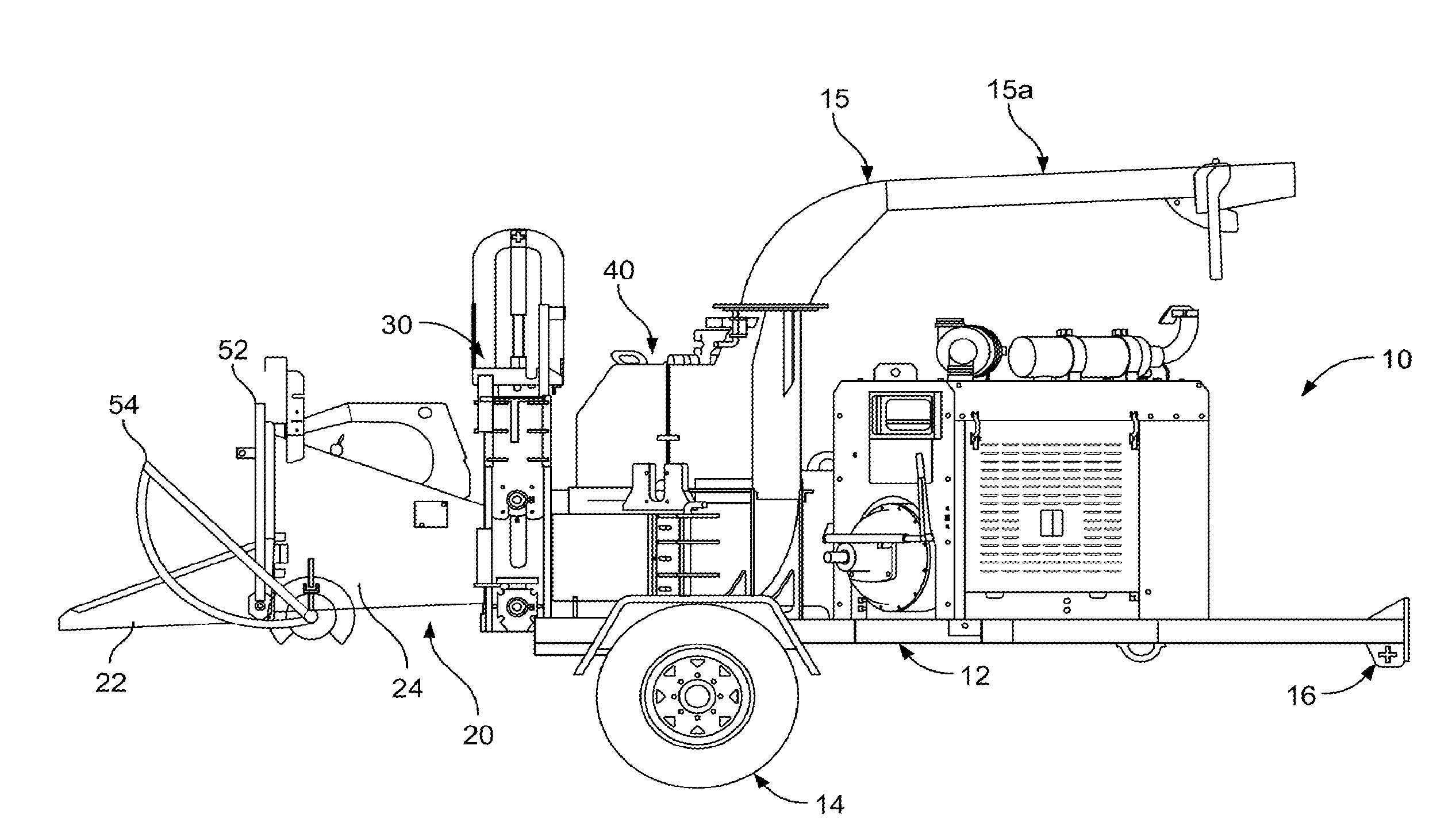
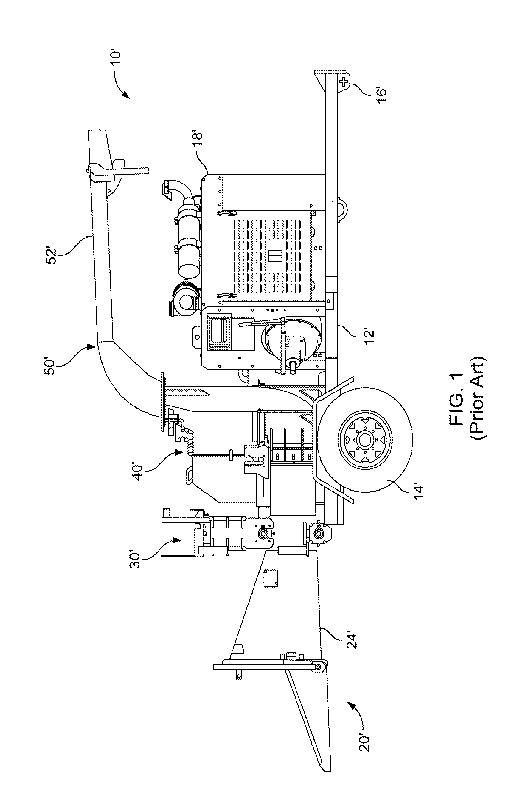
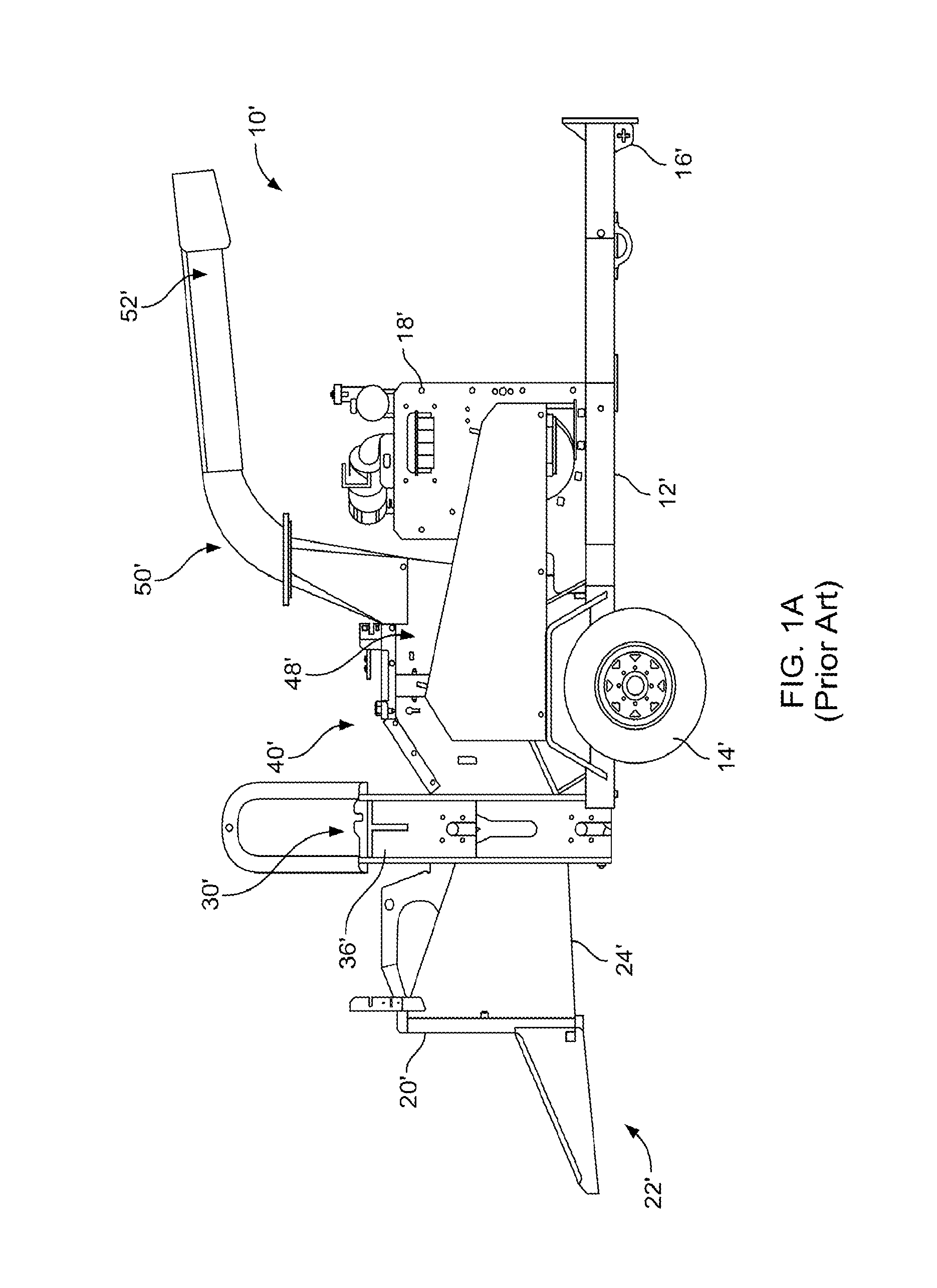
[0079]The disadvantages and drawbacks of the prior art are overcome through the waste processing system of the present invention, wherein one preferred embodiment 10 is disclosed. Referring now to FIG. 2, one embodiment of a waste processing system is shown generally at 10 and includes a frame 12 supported by a pair of wheels 14, and a trailer hitch 16 in order to allow the waste processing system to be transported by a vehicle. Supported on the frame 12 are a cutting system 40, an infeed chute 20, and a discharge chute assembly 15. A power system 18, typically comprising an internal combustion engine, is also mounted on frame 12 to provide power to both a feed system 30 and the cutting system 40.

[0080]As is generally known, operation of waste processing system 10 typically comprises providing power to the cutting system 40 and the feed system 30 through power supply 18, whereby feed system 30 feeds or supplies material to cutting system 40, and cutting system 40 is used to reduce o...

first embodiment

[0086]Referring now to FIGS. 2-7, the safety and control system 60 is illustrated wherein is shown a safety and control system 60 which comprises, inter alia, an actuator 54 having at least two operable positions (e.g., on or off). The safety and control system 60 and actuator 54 are operably connected to or otherwise in communication with one or more of the primary systems of waste processing system 10, and are adapted to selectively control the operation thereof. For illustrative purposes only, the selective control of these systems may comprise selectively powering, driving (forward or reverse), interrupting, stopping, braking, or otherwise operating one or more of the primary systems of the waste processing system including, for example, the power supply 18, the cutting system 40, and the feed system 30. As illustrated, actuator 54 is positioned on a side 101 of the infeed assembly 20. Of course, alternatively and / or in addition to side 101, actuator 54 could be positioned on si...


PUM


Abstract

A waste processing system includes a cutting system and a feed system, wherein the improvement relates to a safety and control system which comprises a side mount actuator having at least two operable positions, wherein the actuator is in communication with the waste processing system and is adapted to selectively control the operation thereof.

Description

CROSS REFERENCE TO RELATED APPLICATION[0001]This application claims the benefit of the filing date of U.S. provisional application Ser. No. 61 / 515,346 entitled “Safety and Control Device, System, and Method Thereof for a Waste Processing System” which was filed on Aug. 5, 2011 and which is herein incorporated by reference.BACKGROUND OF THE INVENTION[0002]The present invention relates to waste processing systems, and more specifically to a safety and control device, a safety and control system, and methods thereof for a waste processing system.[0003]A variety of machines have been developed to recycle, reduce, or otherwise process wood and brush products. Included therein are machines that chip, cut, grind, or otherwise reduce waste (wood) products including, generally, chippers (disk and drum types), hammer mills, hogs, shredders, grinders, and forestry mowers.[0004]These waste processing systems typically include an infeed system and a waste reducing or cutting system, wherein the ...

Claims


Application Information

Patent Timeline
IPC IPC(8): B02C25/00B27L11/00
CPCB02C18/2283B02C18/2291B02C25/00B02C2018/168B02C2201/066B27L11/00
Inventor KENNEDY, RICHARD S.PARKS, SCOTT R.WINNIE, MICHAEL J.ROSE, BILLY JOE
Owner BANDIT IND
Learn More