
Safety and Control Device, System, and Method Thereof for a Waste Processing System

a waste processing and safety device technology, applied in the field of waste processing systems, can solve the problems of catching a user's clothing, affecting the safety of workers, and affecting the operation of waste processing equipment, so as to reduce or prevent the injury of the operator or the equipmen

Inactive Publication Date: 2012-02-23
BANDIT IND
View PDF33 Cites 17 Cited by
  • Summary
  • Abstract
  • Description
  • Claims
  • Application Information

AI Technical Summary

Benefits of technology

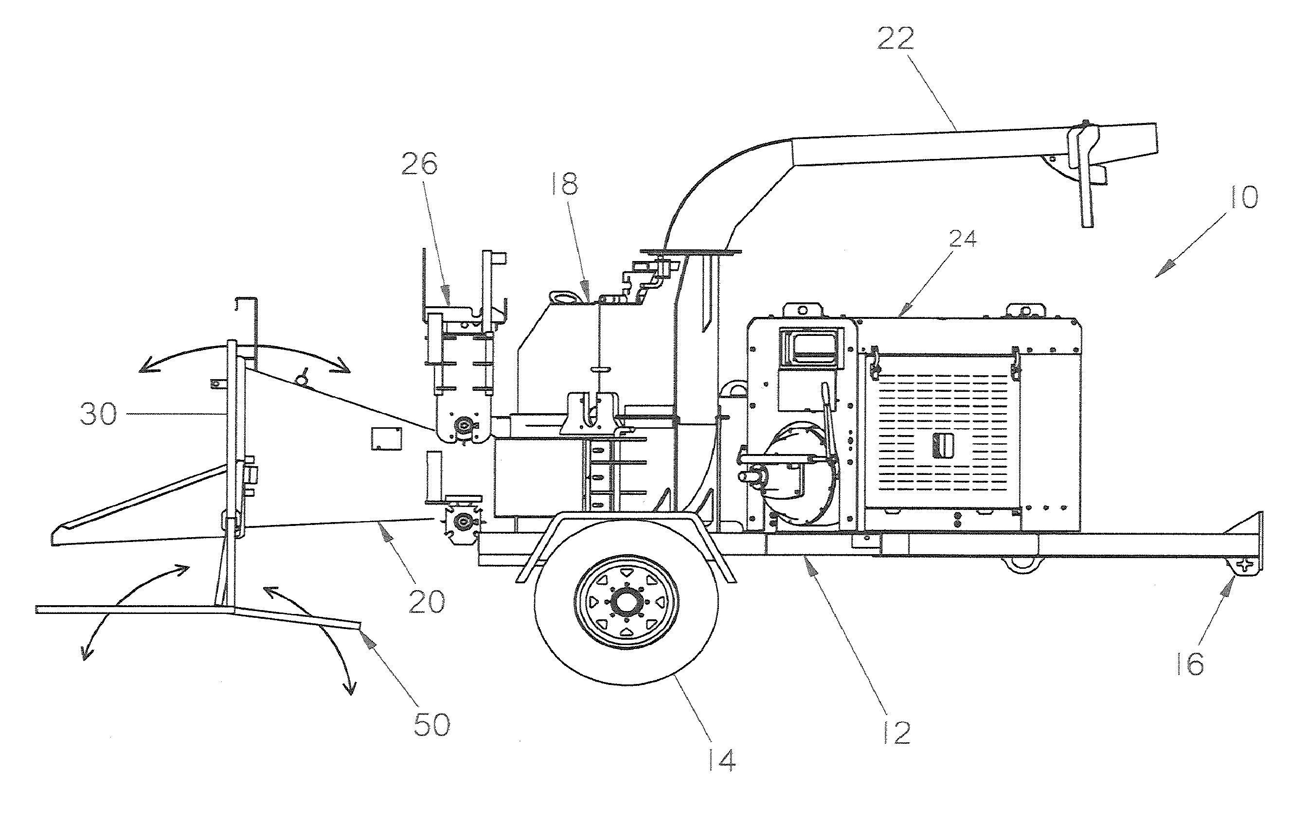
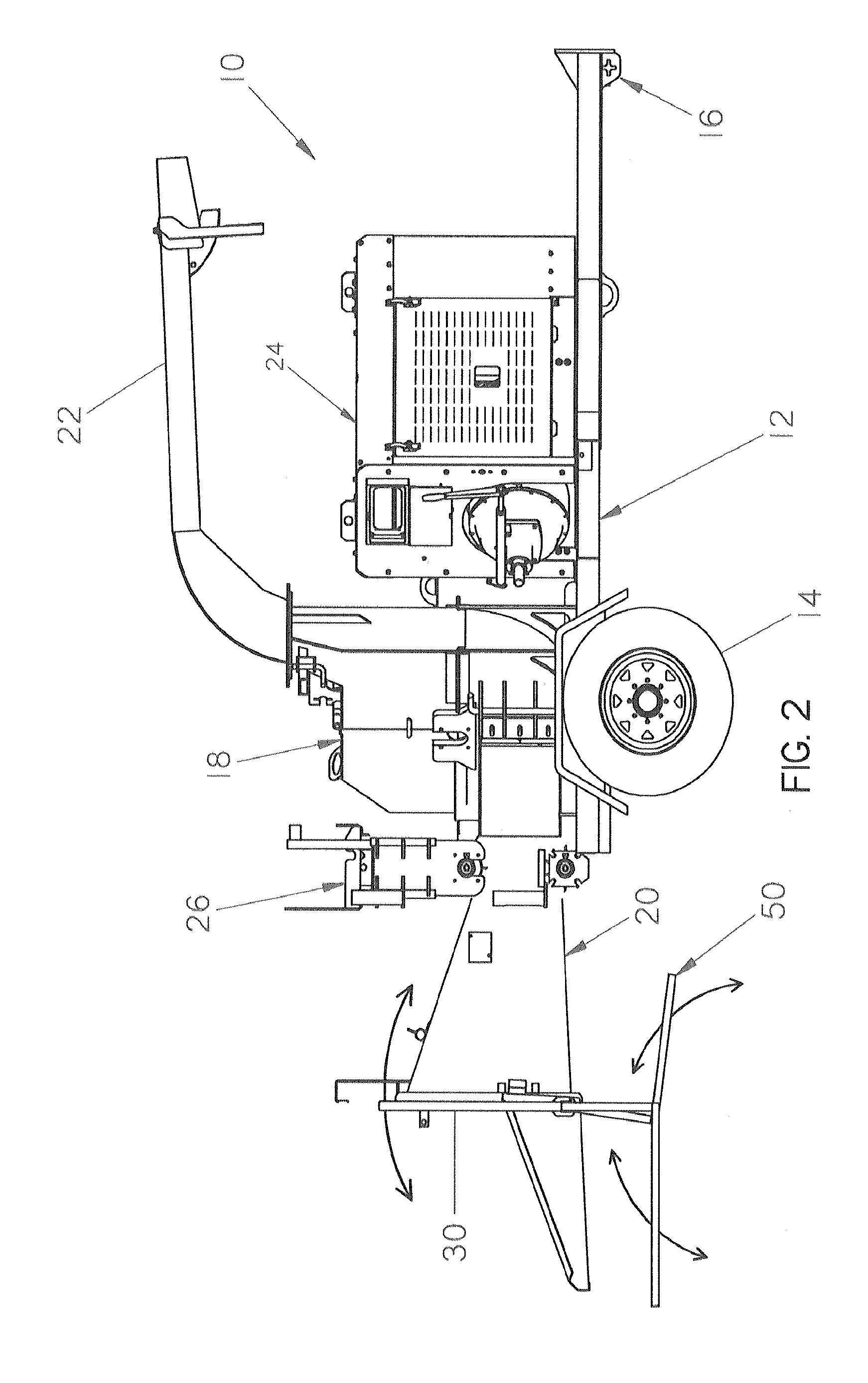
[0010]A waste processing system according to the invention incorporates a control or safety device to stop or otherwise cut-off power to a feed system, a cutting mechanism, or a power system in order to reduce or prevent injury to an operator or the equipment. Alternatively, a device to reverse the feed system, cutting mechanism, or both can be accomplished. The improvement may be utilized in conjunction with any waste reducing machinery, either new or existing, and in one exemplary embodiment, the invention comprises a waste processing system including rotary feed wheels which are powered hydraulically, and in an emergency situation, the system automatically actuates to interrupt or cut-off the supply of hydraulic fluid to the feed wheels of the waste processing system. In another aspect of the invention, the device reverses the flow of hydraulic fluid thereby reversing the direction of rotation of the feed system. The novel devices, systems, and methods disclosed herein can be incorporated into any waste reducing machinery regardless of the drive system, and can be used to cut-off, interrupt, or reverse the power system, the feed system, the cutting blades, or any other primary systems of these waste processing machines. As such, the equipment and operators of these systems are provided with additional protection and safety.

Problems solved by technology

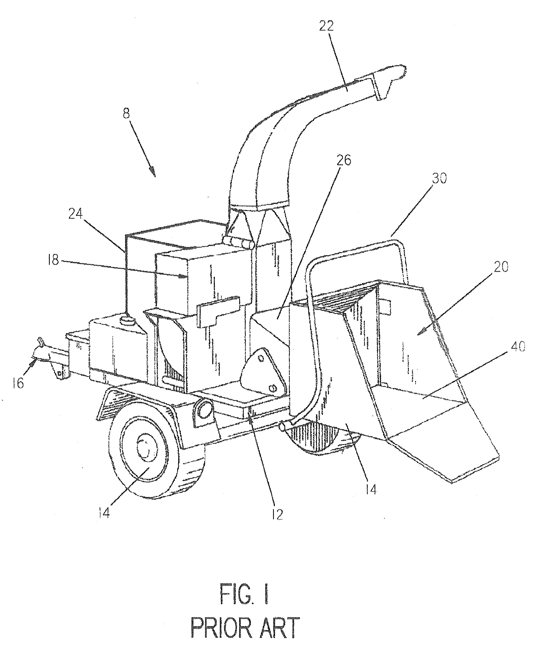
However, although these types of wood chippers are useful, if operated incorrectly they can become extremely dangerous.
For example, the feed system, which is located at the narrowest point of the infeed chute, when operated incorrectly has been known to catch a user's clothing or worse, a limb of an operator.
Another area that may become hazardous if operated incorrectly is the chipping mechanism which can rotate at high speeds in order to produce the high torque necessary to chip the wood and / or waste products.
Further exacerbating the situation is that if something does become entangled in the feed system, the user may not be able to reach or activate a shutoff.

Method used


Image

  • Safety and Control Device, System, and Method Thereof for a Waste Processing System
  • Safety and Control Device, System, and Method Thereof for a Waste Processing System
  • Safety and Control Device, System, and Method Thereof for a Waste Processing System

Examples


Embodiment Construction

[0055]The best mode for carrying out the invention is presented in terms of the preferred embodiment, wherein similar referenced characters designate corresponding features throughout the several figures of the drawings.

[0056]For purposes of description herein, the terms “upper”, “lower”, “right”, “left”, “rear”, “front”, “vertical”, “horizontal”, and derivatives thereof, shall relate to the orientation illustrated in FIG. 1. However, it is to be understood that the invention may assume various alternative orientations, except where expressly specified to the contrary. It is also to be understood that the specific devices and processes illustrated in the attached drawings and described in the following specification are exemplary embodiments of the inventive concepts defined in the appended claims. Hence, specific dimensions and other physical characteristics relating to the embodiments disclosed herein are not to be considered as limiting, unless the claims expressly state otherwis...


PUM

PropertyMeasurementUnit
pressureaaaaaaaaaa
feed rateaaaaaaaaaa
speedsaaaaaaaaaa

Abstract

A waste processing system includes a cutting system and a feed system, wherein the improvement relates to a safety and control system which comprises a foot actuated actuator having at least two operable positions, wherein the actuator is in communication with the waste processing system and is adapted to selectively control the operation thereof.

Description

CROSS REFERENCE To RELATED APPLICATION[0001]This application claims the benefit of the filing date of U.S. provisional application Ser. No. 61 / 174,759 entitled “Safety Device, System, and Method Thereof for a Waste Processing System” which was filed on May 1, 2009 and which is herein incorporated by reference.BACKGROUND OF THE INVENTION[0002]The present invention relates to waste processing systems, and more specifically to a safety device, a safety system, and method thereof for a waste processing system.[0003]A variety of machines have been developed to recycle, reduce, or otherwise process wood and brush products. Included therein are machines that chip, cut, grind, or otherwise reduce waste (wood) products including, generally, chippers (disk and drum types), hammer mills, hogs, shredders, grinders, and forestry mowers.[0004]These waste processing systems typically include an infeed system and a waste reducing system, wherein the infeed system is used for directing the waste mat...

Claims


Application Information

Patent Timeline
Patent Type & Authority Applications(United States)
IPC IPC(8): A01F21/00B02C19/00
CPCB02C25/00B02C2201/066B02C2018/168B02C18/2291
Inventor MOREY, MICHAEL BOYD
Owner BANDIT IND
Learn More