Ultrasonic device, ultrasonic probe, electronic equipment, and ultrasonic imaging apparatus

a technology of ultrasonic devices and ultrasonic probes, applied in measurement devices, mechanical vibration separation, instruments, etc., can solve the problems of difficult formation of acoustic matching layers with desired thicknesses, and achieve the effect of high accuracy and efficient transmission and reception of ultrasound

Inactive Publication Date: 2014-07-31
SEIKO EPSON CORP
View PDF11 Cites 21 Cited by
  • Summary
  • Abstract
  • Description
  • Claims
  • Application Information

AI Technical Summary

Benefits of technology

[0034]The ultrasonic imaging apparatus of this application example includes the ultrasonic device that can set an appropriate thickness of the acoustic matching layer and performs efficient transmission and reception of ultrasound. Thus, it is possible to provide an ultrasonic imaging apparatus with high accuracy.

Problems solved by technology

However, it is difficult to form the acoustic matching layer with a desired thickness in the case of forming the acoustic matching layer using a resin.

Method used


Image

  • Ultrasonic device, ultrasonic probe, electronic equipment, and ultrasonic imaging apparatus
  • Ultrasonic device, ultrasonic probe, electronic equipment, and ultrasonic imaging apparatus
  • Ultrasonic device, ultrasonic probe, electronic equipment, and ultrasonic imaging apparatus

Examples


first embodiment

[0057]In this embodiment, an ultrasonic imaging apparatus for inspecting the inside of the human body is described as an example of electronic equipment.

(1) Overall Configuration of Ultrasonic Imaging Apparatus

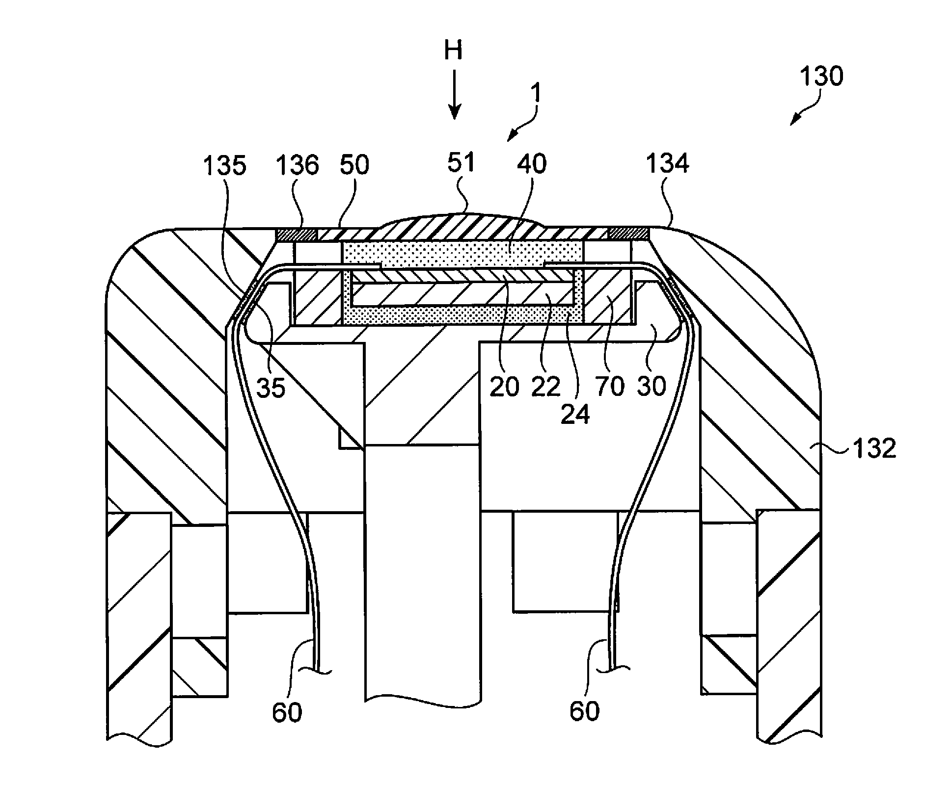
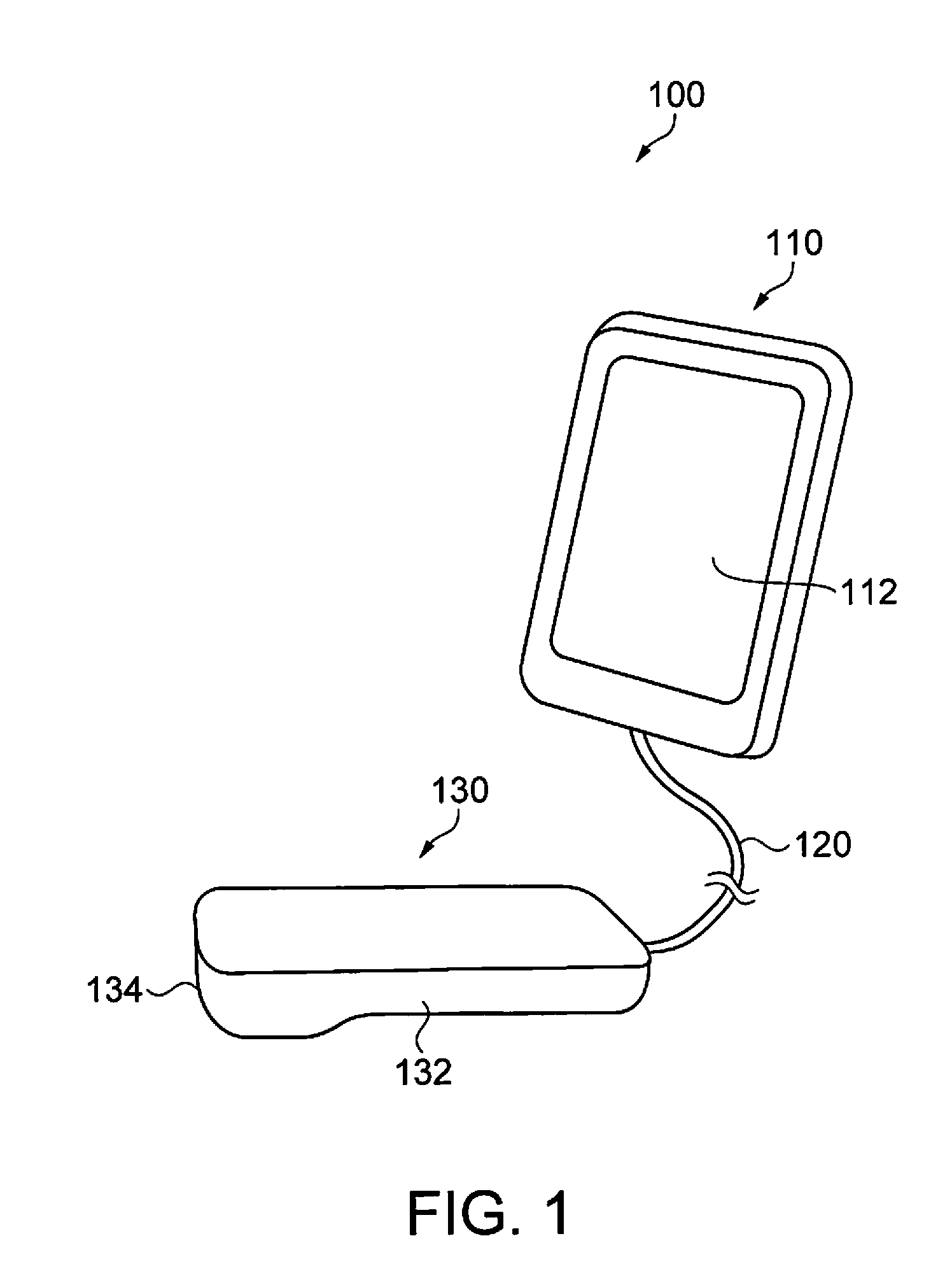
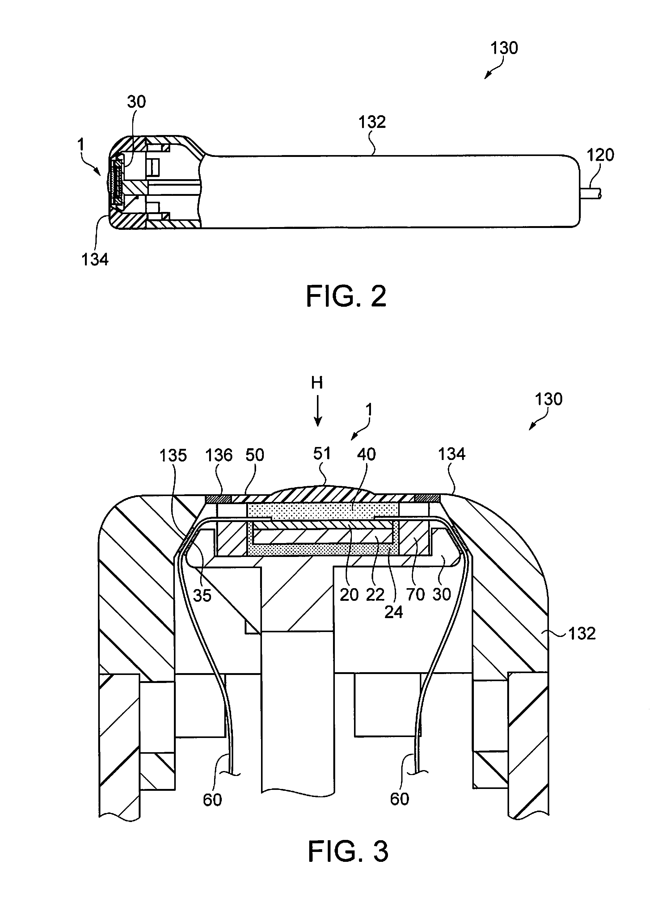
[0058]FIG. 1 shows a schematic outline of an ultrasonic imaging apparatus of this embodiment. FIG. 2 is a partial sectional view of an ultrasonic probe. FIG. 3 is an enlarged sectional view of a head portion of the ultrasonic probe.

[0059]As shown in FIG. 1, an ultrasonic imaging apparatus 100 includes an apparatus body 110 and an ultrasonic probe 130. The apparatus body 110 and the ultrasonic probe 130 are connected to each other by a cable 120. The apparatus body 110 and the ultrasonic probe 130 can exchange electrical signals via the cable 120.

[0060]The apparatus body 110 incorporates a display panel or the like as a display 112. In this embodiment, the display 112 is a touch panel display, and serves also as a user-interface unit (UI unit).

[0061]In the apparatus body 110, i...

second embodiment

[0145]Next, an ultrasonic device of the second embodiment is described.

[0146]FIG. 16 is a sectional view showing a configuration of the ultrasonic device of this embodiment. FIG. 17 is a plan view showing a configuration of a fixing frame, as viewed from the back surface (surface in contact with the ultrasonic element array substrate).

[0147]This embodiment has the same configuration as the first embodiment, except that the fixing frame has a different structure from the first embodiment. Therefore, the same components as in the first embodiment are denoted by the same reference numerals, and the description thereof is omitted.

[0148]An ultrasonic device 4 shown in FIG. 16 is provided with a plurality of first projections 76 in portions, which come into contact with the acoustic lens 50, of the fixing frame 70a. The first projections 76 are provided on each of both sides in the longitudinal direction of the fixing frame 70a, as shown in FIG. 17. The first projections 76 are formed at ...

third embodiment

[0154]Next, an ultrasonic device of the third embodiment is described.

[0155]FIG. 18 is a sectional view showing a configuration of the ultrasonic device of this embodiment. FIG. 19 is a plan view showing a configuration of an acoustic lens.

[0156]This embodiment has the same configuration as the first embodiment, except that the acoustic lens and the fixing frame each have a different structure from the first embodiment. Therefore, the same components as in the first embodiment are denoted by the same reference numerals, and the description thereof is omitted.

[0157]An ultrasonic device 5 shown in FIG. 18 is provided with a plurality of second projections 52 in portions of the acoustic lens 50a that come into contact with the fixing frame 70b. The second projections 52 are provided on each of both sides in the longitudinal direction of the acoustic lens 50a, as shown in FIG. 19.

[0158]The portions of the fixing frame 70b that come into contact with the second projections 52 are formed ...


PUM


Abstract

An ultrasonic device includes an ultrasonic element array substrate having a plurality of ultrasonic elements that each include a piezoelectric body; a fixing frame having a recess to which the ultrasonic element array substrate is fixed, and a perforated portion formed with a through hole by opening a part of the bottom face of the recess, wherein an element-formed surface of the ultrasonic element array substrate is faced to the perforated portion; an acoustic lens secured to the fixing frame so as to cover the perforated portion; and an acoustic matching layer formed of a resin being arranged between the ultrasonic element array substrate and the acoustic lens, so as to secure them to each other. The acoustic lens and the fixing frame are in contact with each other, and the thickness of the acoustic matching layer is maintained at a fixed value.

Description

BACKGROUND[0001]1. Technical Field[0002]The present invention relates to an ultrasonic device, an ultrasonic probe, electronic equipment, and an ultrasonic imaging apparatus.[0003]2. Related Art[0004]Up to the present time, ultrasonic elements that transmit and receive ultrasound have been known. Ultrasonic devices using such ultrasonic elements are used for various applications.[0005]JP-A-2012-100994, which is an example of related art, discloses an ultrasonic device used, for example, for an ultrasonic probe provided with: ultrasonic transducers (ultrasonic elements) that transmit and receive ultrasound; an acoustic lens that focuses the ultrasound; and an acoustic matching layer provided between the acoustic lens and the ultrasonic transducers.[0006]In the ultrasonic device having such a structure, the acoustic matching layer is formed to have a specific thickness, in order to prevent the ultrasound from being reflected by an interface through which the ultrasound passes. The thi...

Claims


Application Information

Patent Timeline
Patent Type & Authority Applications(United States)
IPC IPC(8): G01S7/52G01S15/02
CPCG01S15/02G01S7/52053B06B1/0629G01S7/52079G01S7/5208G01S15/8925G10K11/02G10K11/30
Inventor KIYOSE, KANECHIKA
Owner SEIKO EPSON CORP
Why Eureka
Try Eureka