Connector and method for the production thereof

a technology of connecting pins and connectors, applied in the direction of connecting, electrical apparatus, coupling device connections, etc., can solve the problems of requiring a considerable amount of space on the printed circuit board, complex configuration of such a plug connector of several individual parts, etc., to prevent the appearance of erroneous electrical contacts, and reduce the cost of production

Inactive Publication Date: 2014-08-07
ERNI PRODION GMBH
View PDF4 Cites 5 Cited by
  • Summary
  • Abstract
  • Description
  • Claims
  • Application Information

AI Technical Summary

Benefits of technology

[0007]This object is achieved by a connector with the features of claim 1 and by a method for producing such a connector with the features of claim 10.
[0008]It is the fundamental idea of the invention to arrange the lateral tabs which are formed on the base plate of the connector and which are bent twice substantially at a right angle and surround the plug connector housing at the edge in such a way that the fastening openings on the front and rear side of the connector are covered by the tabs in the surrounded state of the plug connector housing. At the same time, a positioning pin is arranged on the tabs, namely on the portion of the tabs which are bent off once. As a result of bending the base plate about the edge of the plug housing, a secure fastening of the plug housing on the base plate and simultaneous shielding are produced, which fastening can be produced in a simple way. Furthermore, it is especially advantageous that the positioning pins are arranged on the side of the tabs which are bent off once. The positioning pins are integrally arranged with the base plate and are therefore arranged on an extension of the plate. As a result of the arrangement on the side which is bent off once, this plate on which the positioning pins are arranged is aligned in the mounted state parallel to the plug-in direction and not perpendicularly to the plug-in direction. This offers great advantages especially in view of bending, and an arrangement of the positioning pins on a plate perpendicularly to the plug-in direction can be bent off in a substantially easier way than an arrangement of the positioning pins on a plate which is arranged parallel to the plug-in direction. In this case, the bending forces are several times higher, so that bending of the positioning pins necessary for the precise positioning of the plug connector cannot be expected.
[0009]Advantageous further developments and improvements of the plug connector stated in the independent claim 1 is possible by the measures mentioned in the dependent claims. An advantageous embodiment thus provides for example that the lateral tabs respectively comprise two beads which are arranged in the region of the rectangular bending and are used for defined bending off. These beads allow a defined and precise bending-off in a highly advantageous manner.
[0010]The plug connector housing comprises a plastic body in which plug contacts and terminal contacts for a printed circuit board are arranged. Said plastic body is fixed to the base plate, e.g. injected-molded onto said base plate. The plug contacts are blade contacts or spring contacts for example. The terminal contacts for the printed circuit board are preferably SMD contacts, i.e. contacts which have been fixed by surface mount technology to the printed circuit board.
[0011]Such a connector is especially positioned at the edge of a printed circuit board. It should take up as little space as possible.
[0012]It is preferably provided in order to prevent that erroneous electrical contacts occur that the plug connector housing comprises a plastic tab for insulation of the contact elements in the plug connector on the rear side thereof. Said plastic tab covers the plug contact elements and / or the terminal contacts of the printed circuit board and / or the connecting lines between the plug contacts and the terminal contacts. Said plastic tab can be coupled in a foldable manner in an especially advantageous way to the connector housing. Secure insulation can be achieved in this case after establishing the contact by simply folding down and latching the plastic tab onto the plug connector housing. An especially advantageous embodiment which can be produced in an especially simple way provides that the foldable tab is injection-molded onto the plug connector housing.

Problems solved by technology

The connector has a relatively large general configuration and therefore requires a considerable amount of space on the printed circuit board.
The configuration of such a plug connector of several individual parts is complex and requires the handling of the different individual parts during mounting.

Method used


Image

  • Connector and method for the production thereof
  • Connector and method for the production thereof
  • Connector and method for the production thereof

Examples


Embodiment Construction

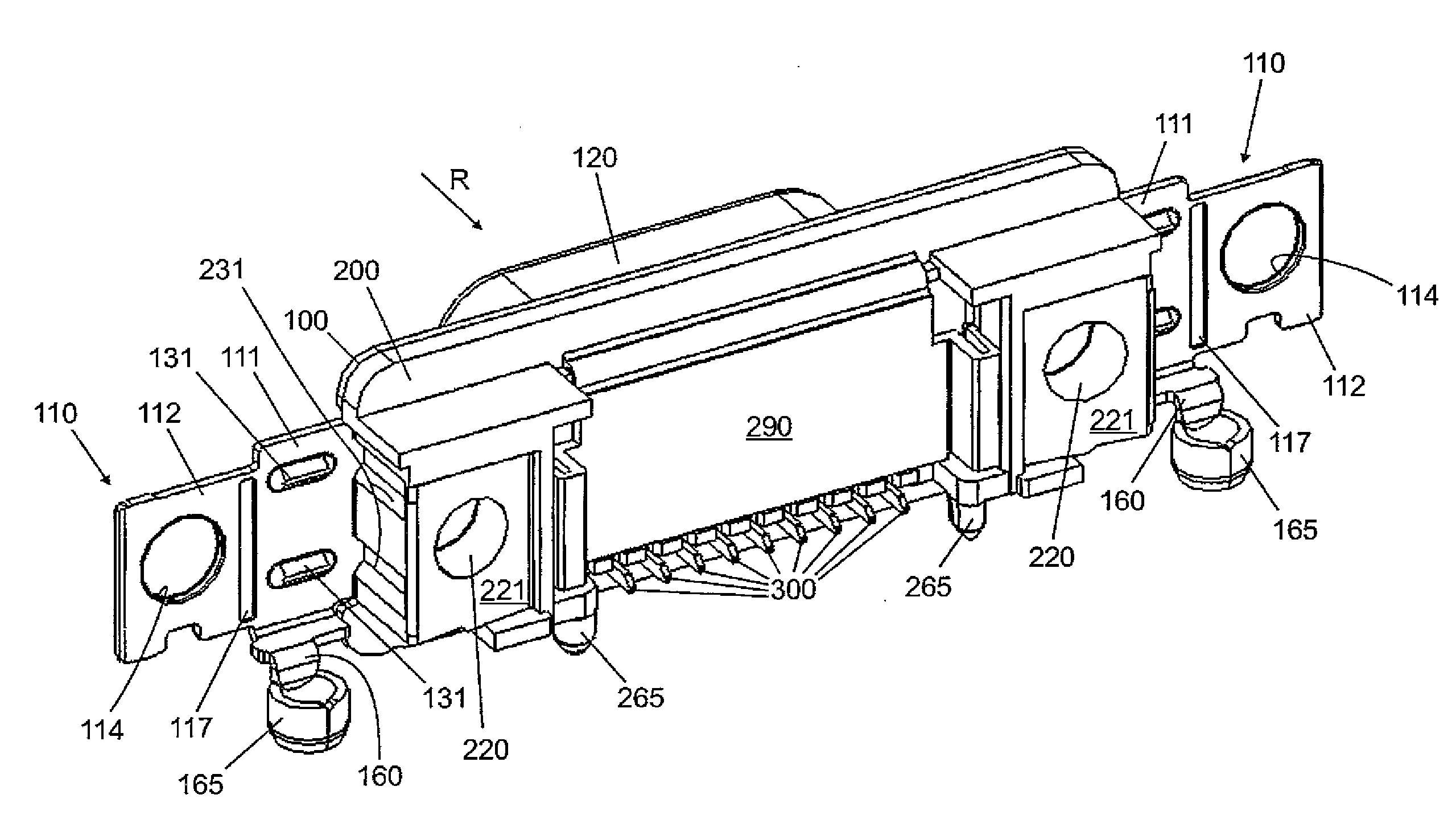
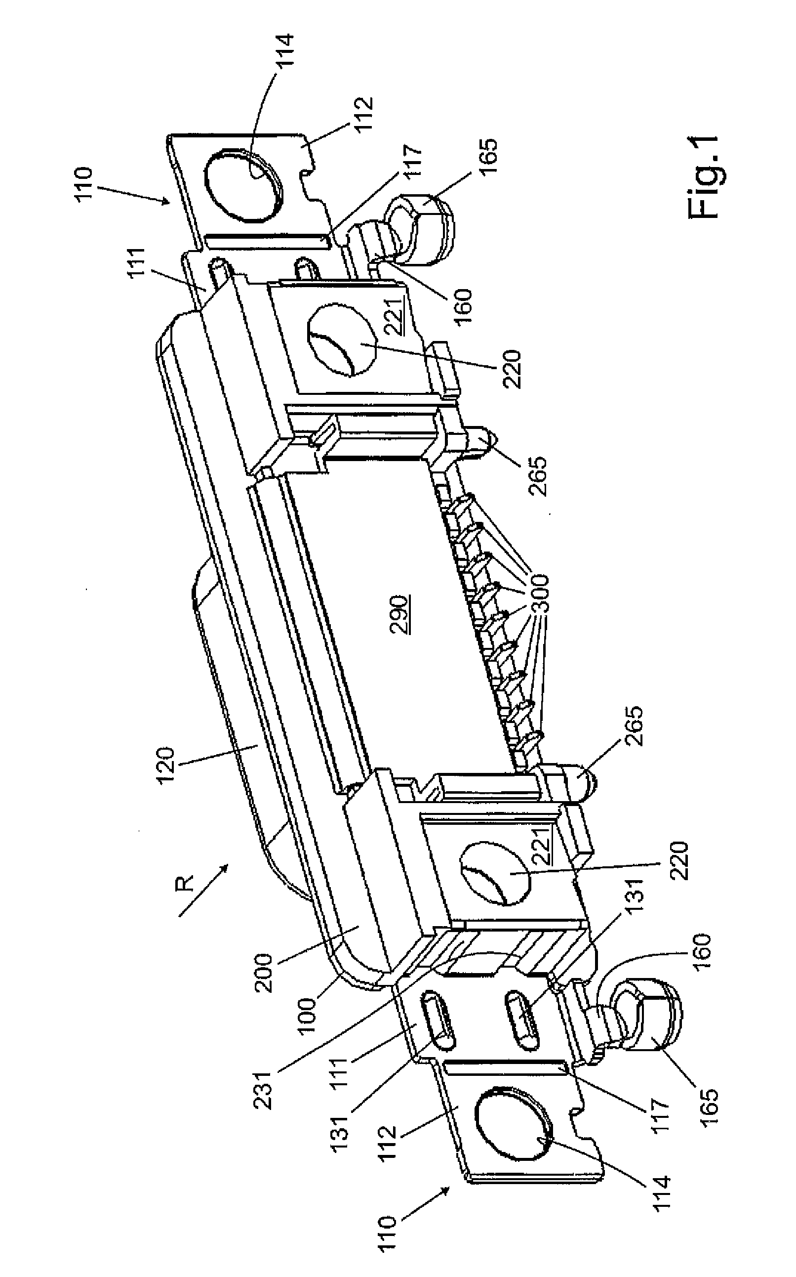
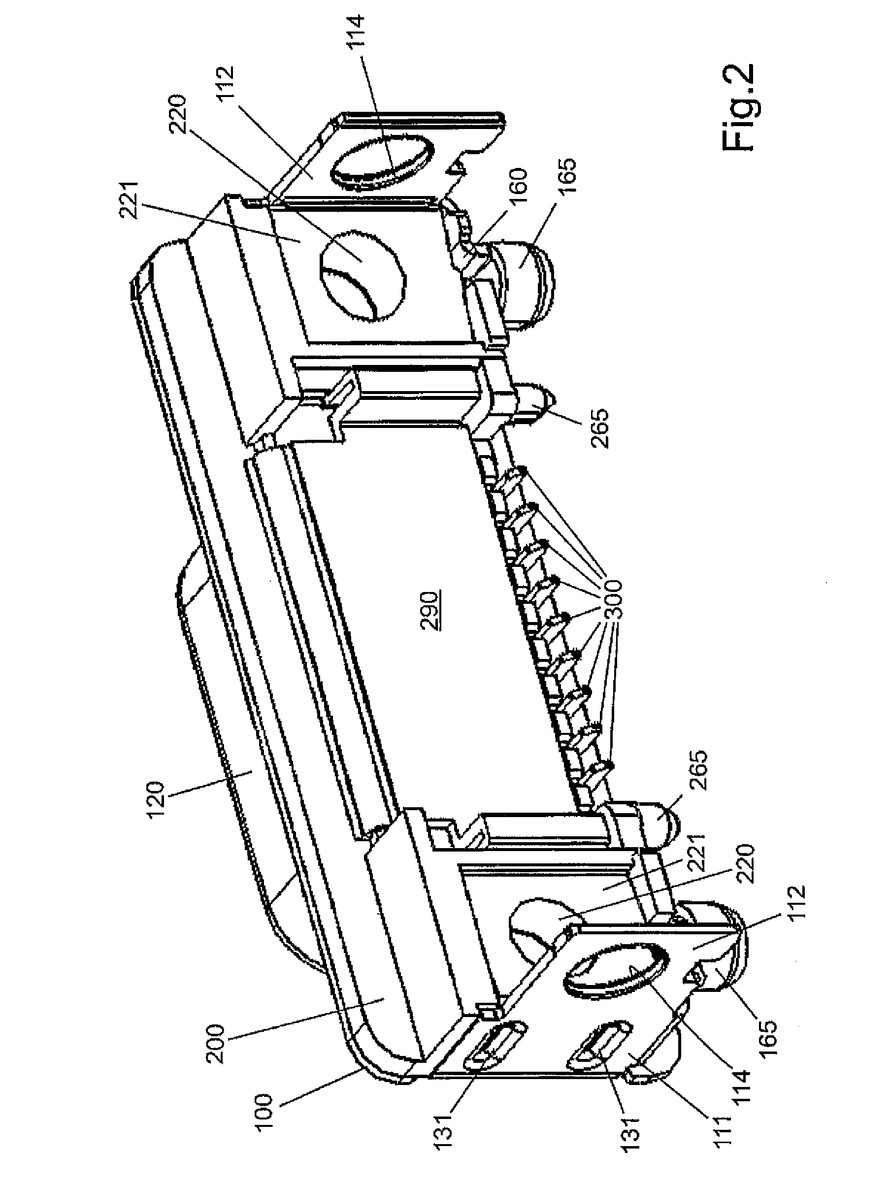
[0018]A sub-D connector or also D-sub connector, which is shown in FIGS. 1 to 4 in an isometric view during various production steps and in FIG. 5 obliquely from the front, comprises a base plate 100, on which a plug connector housing 200 is fixed, e.g. glued or injection-molded. A skirt 120, which is generally known and integrally connected to the base plate 100, is arranged on its front side, said skirt surrounding an opening 122 in which the plug contacts such as spring contact elements or blade contact elements 400 are arranged. The plug connector housing 200 which consists of plastic respectively comprises two lateral openings 220 which are used for accommodating screws, bolts or the like for fixing the connector to a housing wall for example. Accordingly, the base plate 100 also comprises openings 114, of which only one thereof is shown in FIGS. 1 to 4. The other opening 115 is arranged on the front side of the connector and is in alignment with the opening 220 of the plug con...


PUM


Abstract

A Sub-D connector has a base sheet, to which a plug connector is fastened, and positioning journals for positioning on a printed circuit board and lateral fastening openings for receiving fastening screws or fastening pins, wherein the base sheet comprises lateral tabs which are bent twice essentially at a right angle and surround a plug connector housing at the edges. In the state where the tabs are bent twice, the fastening openings on the front and rear side of the connector are covered by the tabs and the positioning journals are arranged on the part of the tabs which is bent once.

Description

[0001]The invention relates to a so-called sub-D connector and a method for its production of the kind according to the independent claims.DESCRIPTION OF THE PRIOR ART[0002]Such connectors are widely used in the state of the art and are used in computers for example. Such connectors are disclosed for example in US 2011 / 0059653 A1, EP 0 648 382 B1 and EP 0 874 421 A1.[0003]A blade connector and a seal for such a blade connector with a base plate are further known from DE 20 2006 018 042 U1, on which a so-called skirt is arranged which surrounds the pin-like plug contacts. Lateral fastening openings in form of boreholes are arranged on the base plate. The connector is fixed in a housing wall for example.[0004]A sub-D connector in SMD technology is known from EP 0 874 421, comprising a base plate which can be fixed to a printed circuit board. The base plate comprises at least one solder projection which is arranged in such a way that it can be soldered by means of SM soldering techniqu...

Claims


Application Information

Patent Timeline
Patent Type & Authority Applications(United States)
IPC IPC(8): H01R13/621
CPCH01R13/621H01R12/7052H01R12/7064H01R12/722H01R13/6215H01R13/6594
Inventor LAPPOEHN, JUERGEN
Owner ERNI PRODION GMBH
Why Eureka
Try Eureka