Functional film, liquid immersion member, method of manufacturing liquid immersion member, exposure apparatus, and device manufacturing method

a technology of liquid immersion member and manufacturing method, which is applied in the direction of printers, knitting, other chemical processes, etc., can solve the problems of increasing cleaning time and frequency, deteriorating productivity, and exposure defects, so as to reduce the number of exposure defects and improve productivity , the effect of improving throughpu

Active Publication Date: 2014-08-14
NIKON CORP
View PDF3 Cites 3 Cited by
  • Summary
  • Abstract
  • Description
  • Claims
  • Application Information

AI Technical Summary

Benefits of technology

[0009]An object of an aspect of the present invention is to provide a functional film having a surface property with both hydrophilic and antifouling properties. In addition, another object of an aspect of the present invention is to provide a liquid immersion member, a method of manufacturing a liquid immersion member, and an exposure apparatus which are capable of reducing the number of exposure defects and reducing deteriorations in productivity. Further, another object of an aspect of the present invention is to provide a device manufacturing method which is capable of reducing the number of defective devices and reducing deteriorations in productivity.
[0031]According to aspects of the present invention, it is possible to provide a functional film having a surface property with both hydrophilic and antifouling properties. In addition, according to aspects of the present invention, it is possible to provide a liquid immersion member, a method of manufacturing a liquid immersion member, and an exposure apparatus which are capable of improving throughput, and reducing the number of exposure defects and reducing deteriorations in productivity. Further, according to aspects of the present invention, it is possible to provide a device manufacturing method which is capable of reducing the number of defective devices and reducing deteriorations in productivity.

Problems solved by technology

When the substrate is exposed in a state where the precipitates are attached to the substrate, there is the possibility of exposure defects (such as, for example, a pattern defect formed on the substrate) and a defective device.
For this reason, it is necessary to periodically clean the member having the liquid immersion region formed therein, and to remove the precipitates on the surface, but an increase in the cleaning time and frequency can lead to productivity deterioration.

Method used


Image

  • Functional film, liquid immersion member, method of manufacturing liquid immersion member, exposure apparatus, and device manufacturing method
  • Functional film, liquid immersion member, method of manufacturing liquid immersion member, exposure apparatus, and device manufacturing method
  • Functional film, liquid immersion member, method of manufacturing liquid immersion member, exposure apparatus, and device manufacturing method

Examples


examples

[0079]Hereinafter, the present invention will be described more specifically on the basis of examples studied in order to evaluate the characteristics of the functional film according to the embodiment of the present invention, but the present invention is not limited to these examples.

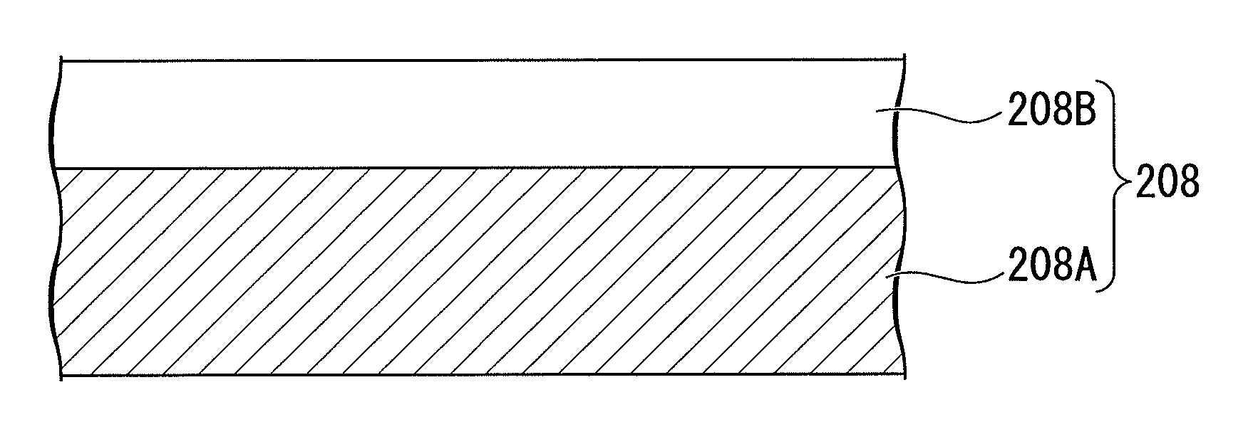
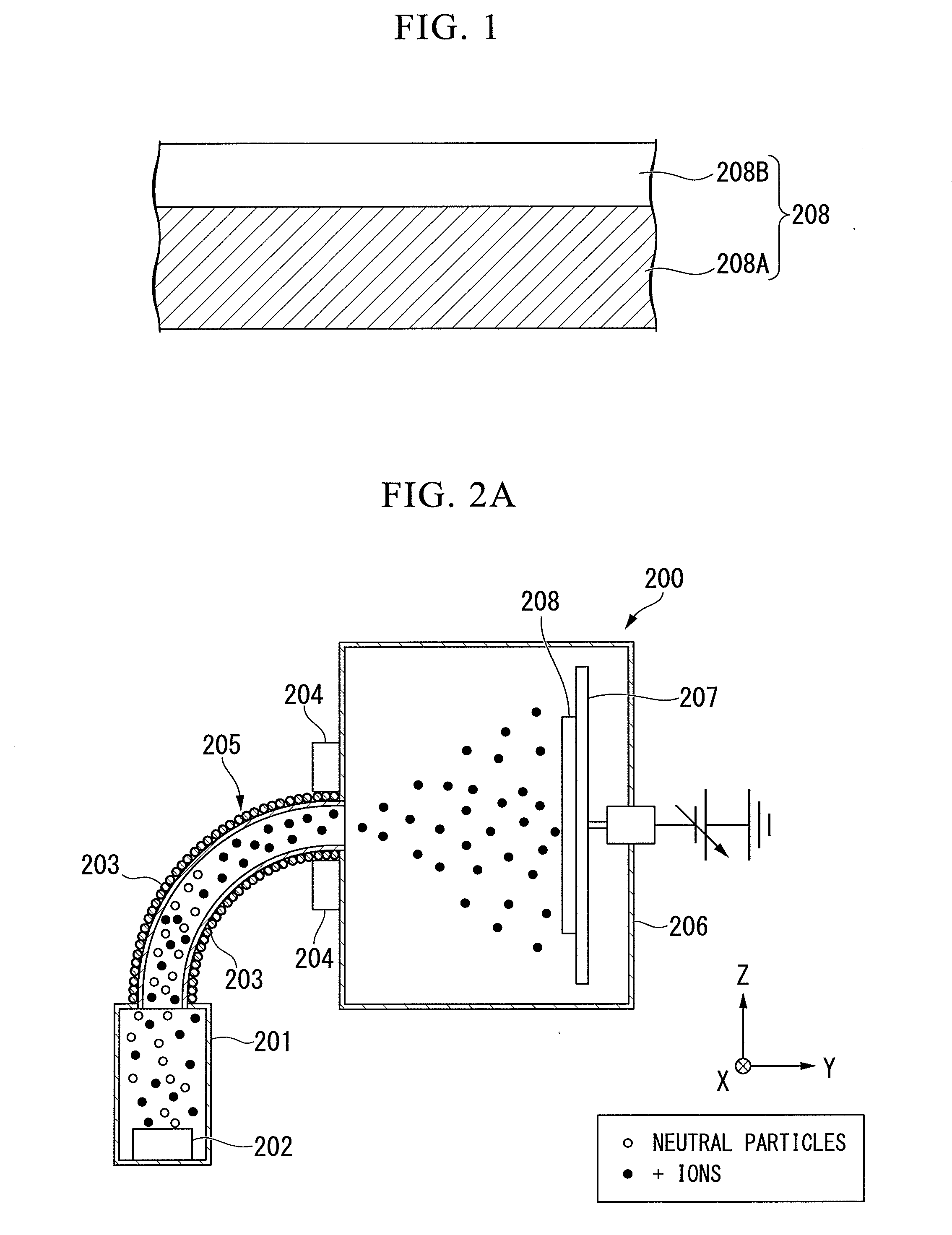
[0080]In the present examples, the sample 208 was fabricated by forming the Ti-doped tetrahedral amorphous carbon film (ta-C:Ti film) 208B as a functional film and the pure Ti film as a comparative experiment, on the base material 208A formed of plate-like Si, and the characteristics thereof were evaluated.

Manufacturing Example

[0081]The base material 208A was ultrasonically cleaned in an organic solvent, an alkaline solution, and pure water. The base material 208A after cleaning was installed so that film formation was performed on one surface (hereinafter, referred to as the A surface), on a base material holder within the deposition chamber of an FCVA film formation apparatus having a configuration ...

first embodiment

[0122]A first embodiment will be described below. FIG. 7 is a schematic configuration diagram showing an example of an exposure apparatus EX according to the first embodiment. In FIG. 7, the exposure apparatus EX includes a mask stage 1 that movably holds a mask M, a substrate stage 2 that movably holds a substrate P, a first drive system 1D that moves the mask stage 1, a second drive system 2D that moves the substrate stage 2, an interferometer system 3 capable of measuring positional information of the mask stage 1 and the substrate stage 2, an illumination system IL that illuminates the mask M with exposure light EL, a projection optical system PL that projects an image of a pattern of the mask M, illuminated with the exposure light EL, onto the substrate P, and a control apparatus 4 that controls an operation of the entire exposure apparatus EX.

[0123]The mask M includes a reticle on which a device pattern projected onto the substrate P is formed. The mask M includes a transmissi...

second embodiment

[0180]Next, a second embodiment will be described. In the following description, configuration portions which are the same as or equivalent to those of the above-mentioned embodiment are denoted by the same reference numerals and signs, and thus the description thereof will be simplified or omitted.

[0181]FIG. 10 is a cross-sectional side view showing a portion of a liquid immersion member 6B according to the second embodiment. As shown in FIG. 10, the lower surface 7 of the liquid immersion member 6B is constituted by a first land surface 51, and a second land surface 52 provided on the outer circumference of the first land surface, and the first land surface 51 and the second land surface 52 are disposed in substantially the same plane (are flush with each other). The supply channel 36A is formed by the side plate portion 12 provided facing the outer circumferential surface 14 of the terminal optical element 5, and an outer circumferential surface 57. A recovery port 53 includes th...


PUM

PropertyMeasurementUnit
static contact angleaaaaaaaaaa
thicknessaaaaaaaaaa
thicknessaaaaaaaaaa

Abstract

A functional film which is applied to a surface of a base material includes a film of Ti-doped tetrahedral amorphous carbon (ta-C:Ti film).

Description

CROSS-REFERENCE TO RELATED APPLICATION[0001]This application is a non-provisional application claiming priority to and the benefit of U.S. provisional application No. 61 / 755,098, filed on Jan. 22, 2013. The entire contents of which are incorporated herein by reference.BACKGROUND[0002]1. Field of the Invention[0003]The present invention relates to a functional film, a liquid immersion member, a method of manufacturing a liquid immersion member, an exposure apparatus, and a device manufacturing method. More specifically, the present invention relates to a functional film having a surface property with both hydrophilic and antifouling properties, to a liquid immersion member using the functional film, to a method of manufacturing a liquid immersion member, to an exposure apparatus, and to a device manufacturing method.[0004]2. Description of Related Art[0005]In exposure apparatuses used in a photolithography process, a liquid immersion exposure apparatus that exposes a substrate with e...

Claims


Application Information

Patent Timeline
Patent Type & Authority Applications(United States)
IPC IPC(8): G03F7/20
CPCG03F7/2041G03F7/7095C04B35/52G03F7/11G03F7/70341Y10T428/24322Y10T428/265Y10T428/31678Y10T442/10
Inventor KISHIUME, TSUKASATAKI, YUSUKE
Owner NIKON CORP
Why Eureka
Try Eureka