Method and system for the in-situ removal of carbonaceous deposits from heat exchanger tube bundles

a technology of carbonaceous deposits and heat exchanger tubes, which is applied in the direction of flush cleaning, hollow article cleaning, electrostatic cleaning, etc., can solve the problems of reducing the efficiency of the heat exchanger, requiring the operator to consume more energy to achieve the desired degree of temperature change, and the cleaning of heat exchanger tube bundles is a significant source of productivity loss, so as to prevent the release of solvents into the environment and the need for expensive disposal measures, and achieve cost-effective

Active Publication Date: 2014-08-28
T5 TECH
View PDF16 Cites 5 Cited by
  • Summary
  • Abstract
  • Description
  • Claims
  • Application Information

AI Technical Summary

Benefits of technology

[0007]The present invention comprises a method and system for the in-situ cleaning of a heat exchanger tube bundle of carbonaceous deposits. The present invention thus avoids the disadvantages in having to remove a heat exchanger tube bundle from its associated equipment in order to clean it of carbonaceous deposits.
[0009]Embodiments of the present invention also involve the recovery of the contaminated organic solvent. Thus, in embodiments of the present invention, a heat exchanger tube bundle may be cleaned in a way that generates a minimal environmental impact. For example, after use in the heat exchanger tube bundle cleaning process, the organic solvent may be treated and then again used in the cleaning of a heat exchanger tube bundle, thereby preventing both the release of the solvent into the environment and the need for expensive disposal measures. By selecting an organic solvent that can be cost-effectively separated from suspended hydrocarbons, embodiments of the present invention also provide a more efficient method for the cleaning of a heat exchanger tube bundle. Further, using embodiments of the present invention, hydrocarbons that are separated from the organic solvent can be collected and / or treated to provide useful products. Thus, embodiments of the present invention both lower the environmental impact of the cleaning process and create a more cost-effective process.

Problems solved by technology

During use, carbonaceous deposits including heavy oil, bitumen, and other hydrocarbons can form on the tube bundles, reducing the effectiveness of the heat exchanger and forcing the operator to consume more energy to achieve the desired degree of temperature change.
Because this process is time consuming, the cleaning of heat exchanger tube bundles is a significant source of lost productivity.
Additionally, the periodic disassembly and handling of the heat exchanger tube bundles and other system equipment inevitably shortens their lifespan.

Method used


Image

  • Method and system for the in-situ removal of carbonaceous deposits from heat exchanger tube bundles
  • Method and system for the in-situ removal of carbonaceous deposits from heat exchanger tube bundles
  • Method and system for the in-situ removal of carbonaceous deposits from heat exchanger tube bundles

Examples


Embodiment Construction

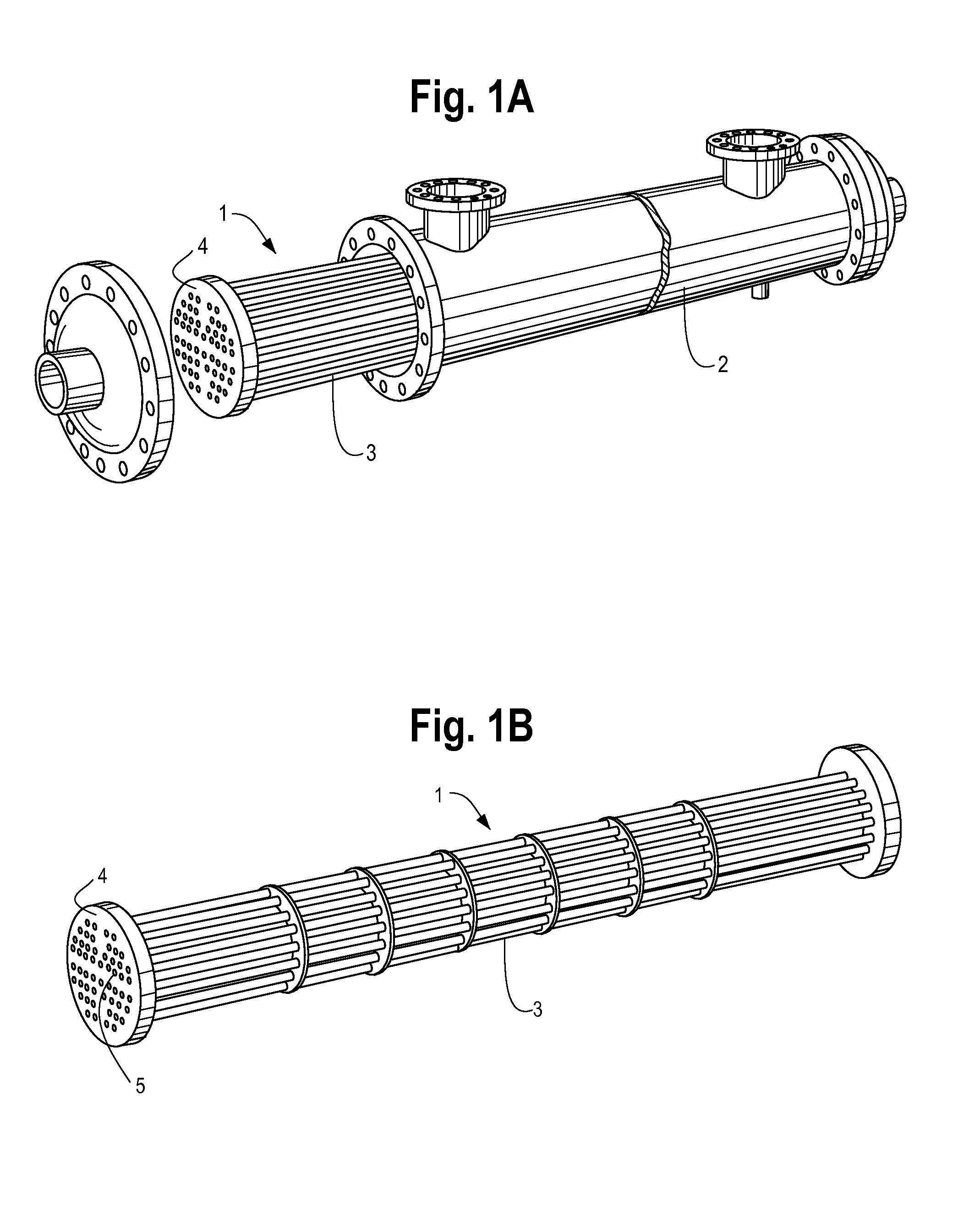
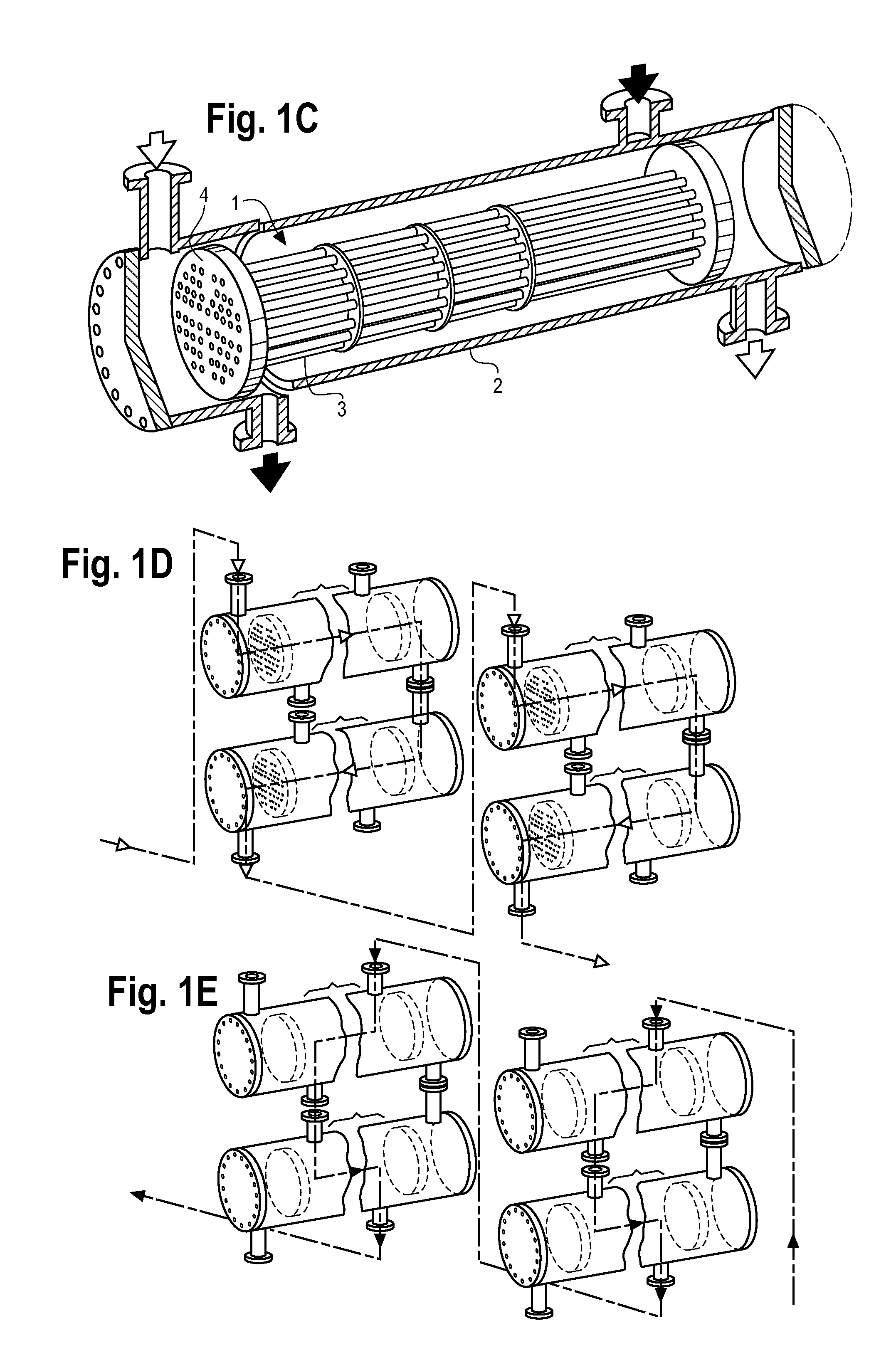
[0025]A heat exchanger tube bundle of the type that may be treated by the present invention is illustrated in FIGS. 1A to 1C. A heat exchanger tube bundle 1 is made up of a large number of individual tubes packed together to form a cylindrical structure. When in use, the heat exchanger tube bundle is surrounded by a shell 2. Accordingly, a heat exchanger tube bundle 1 comprises an exterior, or shell-side, surface 3 and an interior, tube-side, surface 4. Heat exchanger bundles are often very large, typically ranging up to 84 inches in diameter and 30 feet in length. When used in certain industries, such as the gas and oil industry, a number of heat exchanger tube bundles are often used in series in a network known as a heat exchanger train 5, examples of which are illustrated in FIGS. 1D to 1E and FIG. 2.

[0026]Through the method and system of the present invention, a heat exchanger tube bundle 1 may be cleaned in-situ, that is, without being removed from the associated equipment with...


PUM


Abstract

The present invention comprises a method and system for the in-situ cleaning of a heat exchanger tube bundle of carbonaceous deposits. Using the method and system, an organic solvent is brought into fluid communication with one or more heat exchanger tube bundles in a closed system. The closed system is formed at the site of operation of the heat exchanger tube bundles and without having to remove the heat exchanger tube bundles from their shells or other associated equipment. Once the closed system is formed, the organic solvent is brought to a temperature at which it is effective to remove carbonaceous deposits from the heat exchanger tube bundle and flowed through the equipment associated with the heat exchanger tube bundles so as to contact the heat exchanger tube bundles and remove carbonaceous deposits that have formed therein. In some embodiments, the spent organic solvent may be recovered, such as through the removal of suspended hydrocarbons, and reused in the method and system for cleaning heat exchanger tube bundles.

Description

[0001]This application claims priority to U.S. Provisional Application No. 61 / 769,529, filed on Feb. 26, 2013.BACKGROUND OF THE INVENTION[0002]1. Field of the Invention[0003]The present invention relates generally to a method and system for removing carbonaceous deposits from heat exchanger tube bundles. More particularly, the present invention relates to a method and system for thoroughly and efficiently cleaning heat exchanger tube bundles without having to remove the heat exchanger tube bundle from its associated equipment.[0004]2. Description of the Related Art[0005]Heat exchanger tubes bundles are used in a process to either raise or lower the temperature of a fluid. They are heavily used in the oil and gas industry, such as by refineries, upgraders, and gas plants. During use, carbonaceous deposits including heavy oil, bitumen, and other hydrocarbons can form on the tube bundles, reducing the effectiveness of the heat exchanger and forcing the operator to consume more energy t...

Claims


Application Information

Patent Timeline
Patent Type & Authority Applications(United States)
IPC IPC(8): F28G9/00B08B9/032
CPCF28G9/00B08B9/0323B08B3/00B08B3/02B08B3/04B08B3/08B08B3/14B08B9/02B08B9/023B08B9/027B08B9/032F28D7/16
Inventor TOMKINS, MICHAELLARSEN, ROBERT
Owner T5 TECH
Why Eureka
Try Eureka