Connector with force multiplying mechanism and connector assembly provided therewith

a technology of force multiplier and connector, which is applied in the direction of coupling device connection, coupling/disconnecting parts engagement, electrical apparatus, etc., can solve the problems of sliding sliding inadvertently and complicated configuration

Active Publication Date: 2014-08-28
SUMITOMO WIRING SYST LTD
View PDF3 Cites 6 Cited by
  • Summary
  • Abstract
  • Description
  • Claims
  • Application Information

AI Technical Summary

Benefits of technology

[0018]At least one inner lip is formed on the inner peripheral surface of each wire insertion hole and closely contacts an insulation coating of the wire, and an axial position of the narrowed portion in the positioning hole is aligned with the positions of the top of the inner lip. Thus, the wire insulation coating is sealed more effectively.
[0019]Plural positioning holes preferably are arranged at diagonally symmetric positions with respect to the wire insertion hole. This, configuration contributes to making sealing forces for the wires circumferentially uniform while narrowing intervals between the respective wire insertion holes as much as possible.
[0020]The slider partly projects out from the housing when at the movement start position. External matter may contact the projecting end and may exert an external force in a pushing direction. Thus, the lock may be released from the locking state and the slider may move toward the movement end position. However, the protecting edge of the lever is at substantially the same position as or behind the projecting end part when the slider is at the initial position. Thus, a pushing force by the external matter acts first on the protecting edge rather than on the slider. The distance from the rotary shaft to the protecting edge of the lever is set to be shorter than the distance to the operating portion. Thus, a force necessary to release the lock means is larger when it acts on the protecting edge than when it directly acts on the projecting end part of the slider. Thus, the configuration can alleviate a situation where the slider is pushed inadvertently to the movement end position.

Problems solved by technology

Hence, there has been a problem that the slider is pushed inadvertently.
Thus, the connector of Japanese Patent Publication No. 4659069 has a complicated configuration.

Method used


Image

  • Connector with force multiplying mechanism and connector assembly provided therewith
  • Connector with force multiplying mechanism and connector assembly provided therewith
  • Connector with force multiplying mechanism and connector assembly provided therewith

Examples


Embodiment Construction

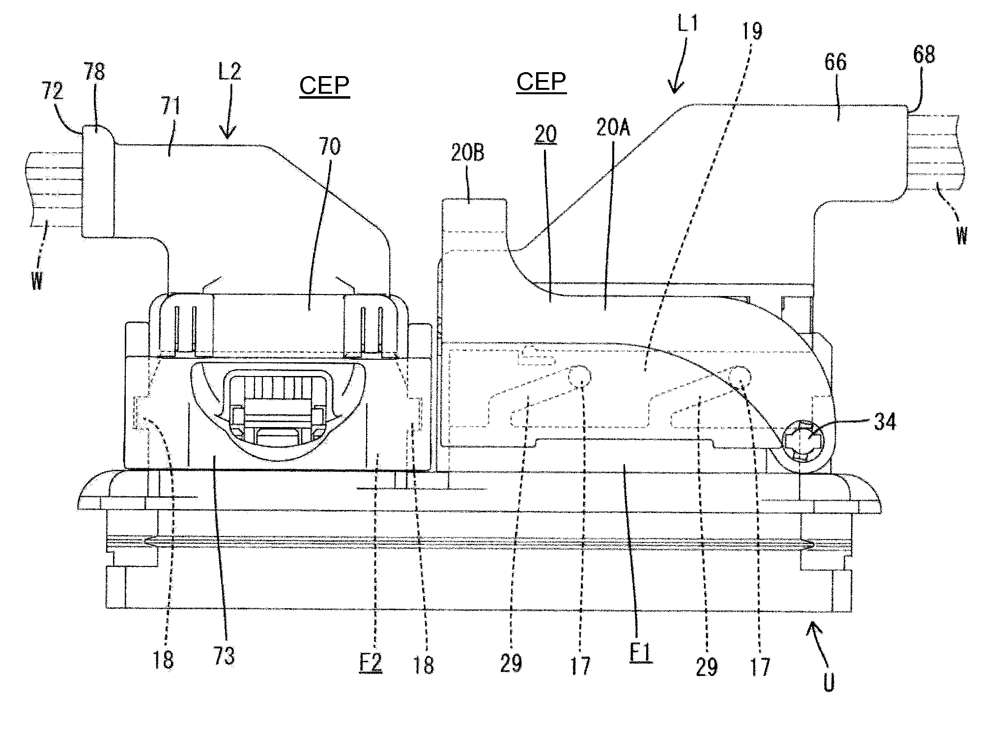
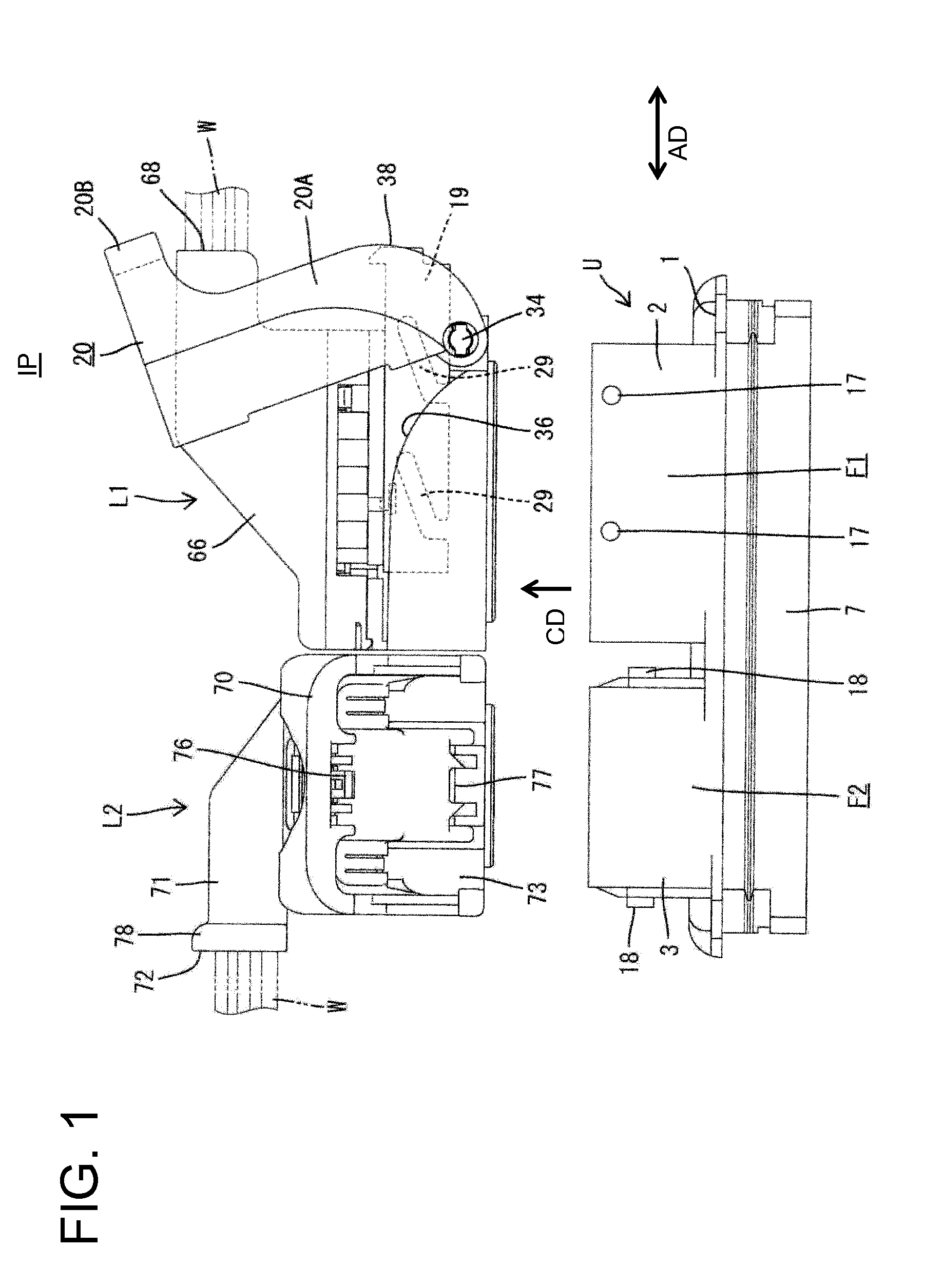
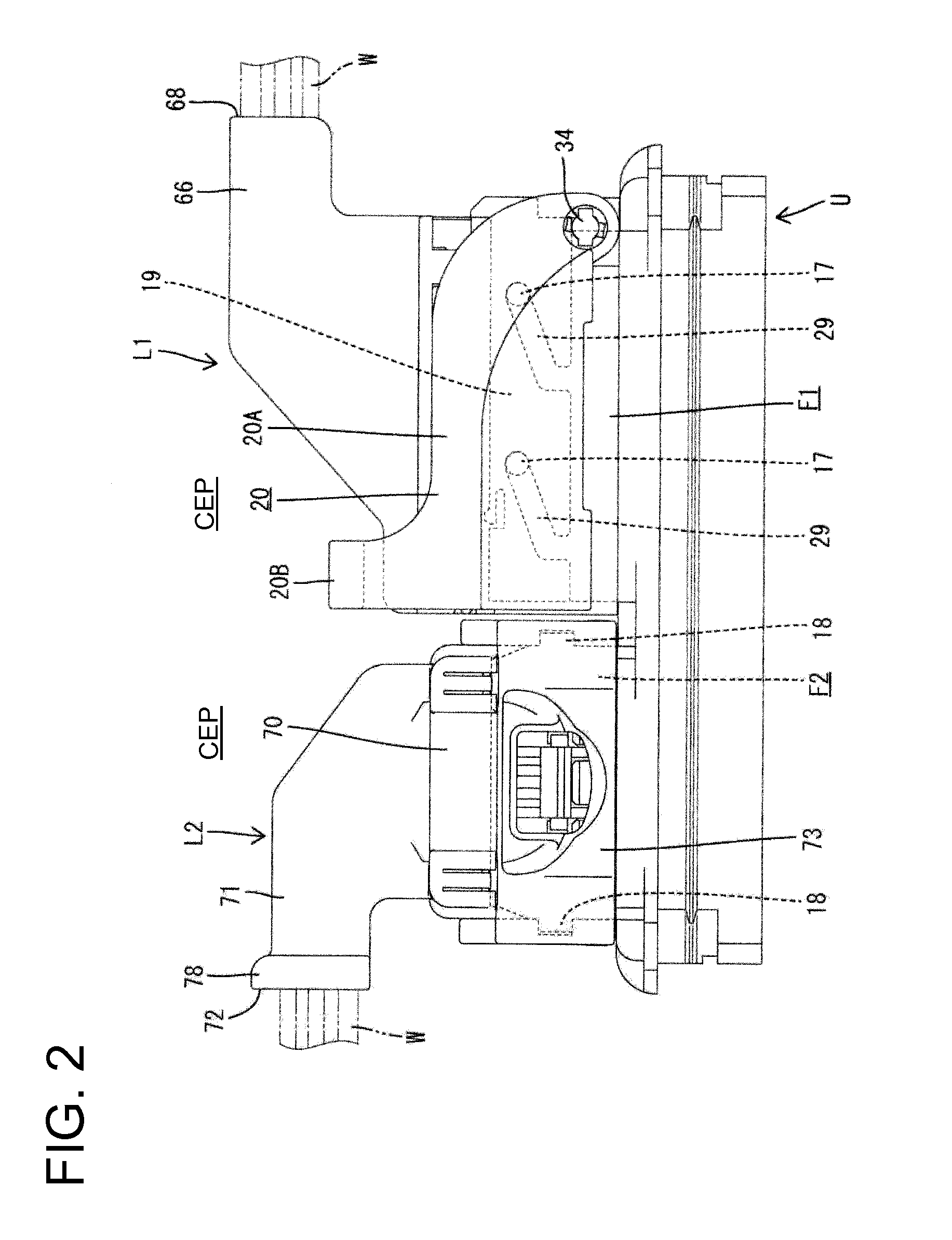
[0057]A connector with the force multiplying mechanism in accordance with the invention includes a fixed-side connector unit U with first and second fixed connectors F1, F2 arranged substantially side by side on a board 1, as shown in FIGS. 1 and 2. First and second lever connectors L1, L2 connectable to the respective fixed-side connectors F1, F2.

[0058]The fixed-side connector unit U includes the board 1 and the first and second fixed connectors F1, F2 mounted on the board 1. As shown in FIG. 3, the first and second fixed connectors F1, F2 are mounted on the board 1 so that their long sides are aligned along an arrangement direction of the fixed connectors F1, F2.

[0059]The fixed connectors F1, F2 include substantially rectangular tubular receptacles 2, 3 projecting forward (up in FIG. 1) in a connecting direction CD from the board 1. As shown in FIG. 3, guide projection shafts 4, 5 project unitarily from the back wall of the receptacle 2, 3 toward a connection surface of each fixed...


PUM


Abstract

A slider (19) to be slid by rotating a lever (20) is mounted in a first lever-side connector (L1). The slider (19) is held at an initial position where cam followers (17) provided on the first lever-side connector (L1) can be received into cam grooves (29). When the slider (19) is at the initial position, a part of the slider (19) projects out from the connector. Lever plates (20A) of the lever (20) are so configured that protecting edge portions (38) formed on parts of side edges of the lever plates (20A) are located substantially at the same position as or behind a projecting end part of the slider (19) when the slider (19) is at the initial position. Further, the protecting edge portions (38) are located closer in distance to rotary shafts (34) than an operating portion (20B).

Description

BACKGROUND[0001]1. Field of the Invention[0002]The invention relates to a connector with a force multiplying mechanism and to a connector assembly provided therewith.[0003]2. Description of the Related Art[0004]Known connectors include a force multiplying mechanism to reduce a connection force for male and female connectors. For example, a cam follower is provided on an outer surface of one connector, and a slider is accommodated on the other connector for sliding movement in a direction intersecting a connecting direction. The slider is slid while the cam follower is engaged with a cam groove on the slider. As a result, the connectors are guided to a properly connected state while a force multiplying action is produced.[0005]The slider of many connectors with the above-described configuration projects out from a housing of a connector before connectors are connected. A projecting end of the slider could be contacted by external matter, such as during transportation of the connector...

Claims


Application Information

Patent Timeline
Patent Type & Authority Applications(United States)
IPC IPC(8): H01R13/629
CPCH01R13/62905H01R13/62977H01R13/5208H01R13/5219
Inventor SUZUKI, MASAKAZU
Owner SUMITOMO WIRING SYST LTD
Why Eureka
Try Eureka