Control device for a brake system of a vehicle, brake system for a vehicle and method for operating a brake system of a vehicle

a control device and brake system technology, applied in the direction of braking systems, instruments, analogue processes for specific applications, etc., can solve the problems of limited recuperative efficiency of known simple systems, and achieve adequate recuperative efficiency of brake systems, limited recuperative efficiency, and minimal additional costs

Active Publication Date: 2014-08-28
ROBERT BOSCH GMBH
View PDF1 Cites 12 Cited by
  • Summary
  • Abstract
  • Description
  • Claims
  • Application Information

AI Technical Summary

Benefits of technology

[0005]The present invention creates a brake system that represents an expanded simple system. Through the expansion, the disadvantage of greatly limited recuperative efficiency of the known simple systems can be remedied without having to make a large work outlay, compared to a conventional brake system, in order to achieve the expansion. Thus, via the present invention it is possible to realize an adequate recuperative efficiency of a brake system in an economical fashion, i.e. with minimal additional costs.
[0006]In particular, the present invention makes it possible to realize a brake system having an advantageous recuperative efficiency whose use is not limited to a vehicle having a brake circuit configured in accordance with axles. Instead, the control device according to the present invention, and the corresponding method for vehicle having a diagonal brake circuit, in which the wheels allocated to a common brake circuit are situated on different vehicle axles, can be advantageously used. A vehicle having a diagonal brake configuration can also be described by saying that the wheels allocated to a common brake circuit are situated diagonally on the vehicle. Thus, the present invention represents an advantageous expansion of a recuperable brake system for vehicles having a diagonal brake circuit configuration.
[0007]In comparison with the existing art, the control device according to the present invention and the corresponding method also offer a masking of a generator braking moment when there is a comparatively strong braking of the vehicle. As is explained in more detail below, through the expansion of the usability of the masking function, a faster charging of a vehicle battery can be realized. Thus, the present invention advantageously contributes to the reduction of energy consumption and exhaust gas emission during the driving of a vehicle.

Problems solved by technology

Through the expansion, the disadvantage of greatly limited recuperative efficiency of the known simple systems can be remedied without having to make a large work outlay, compared to a conventional brake system, in order to achieve the expansion.

Method used


Image

  • Control device for a brake system of a vehicle, brake system for a vehicle and method for operating a brake system of a vehicle
  • Control device for a brake system of a vehicle, brake system for a vehicle and method for operating a brake system of a vehicle
  • Control device for a brake system of a vehicle, brake system for a vehicle and method for operating a brake system of a vehicle

Examples


Embodiment Construction

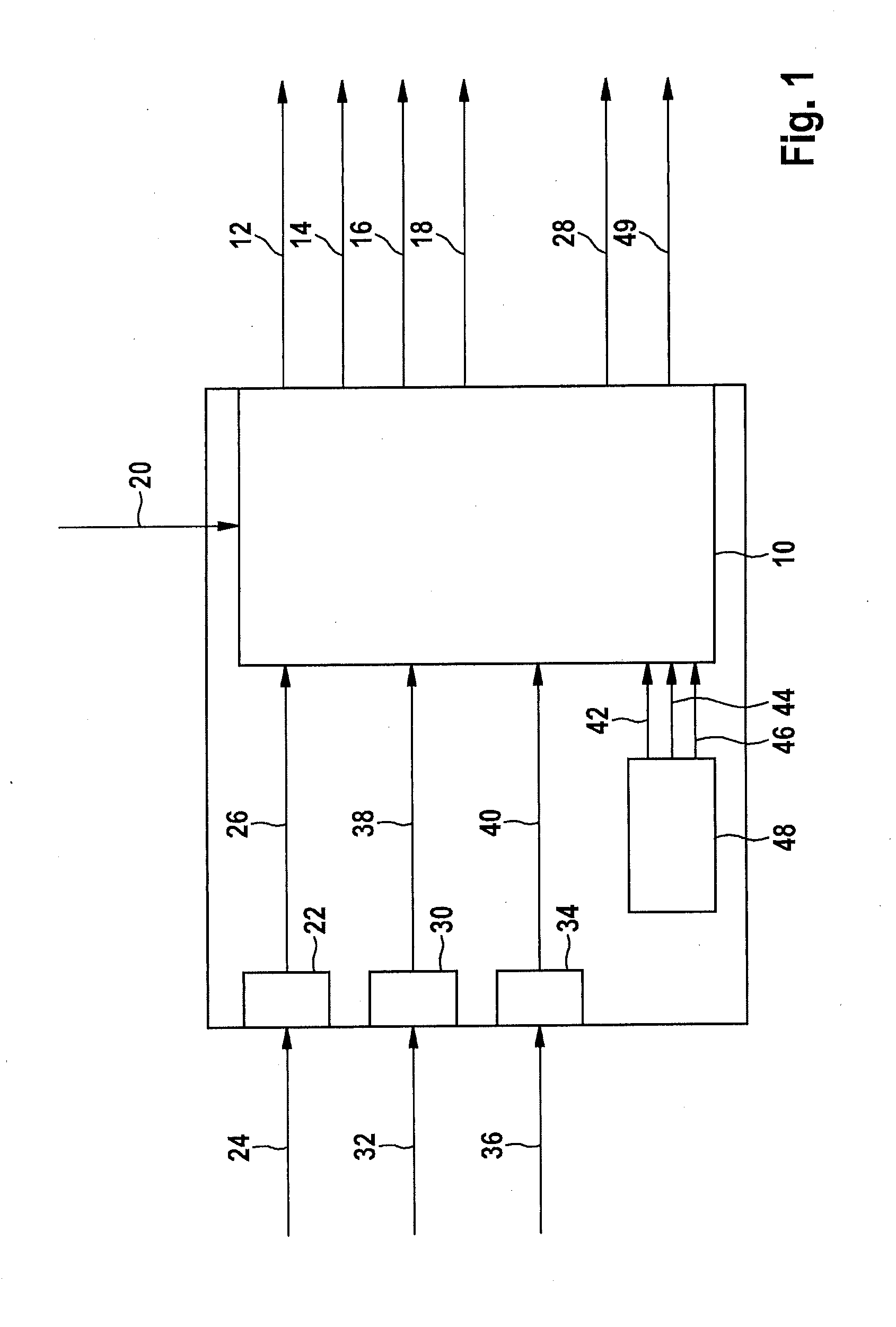
[0014]FIG. 1 shows a schematic representation of a specific embodiment of the control device.

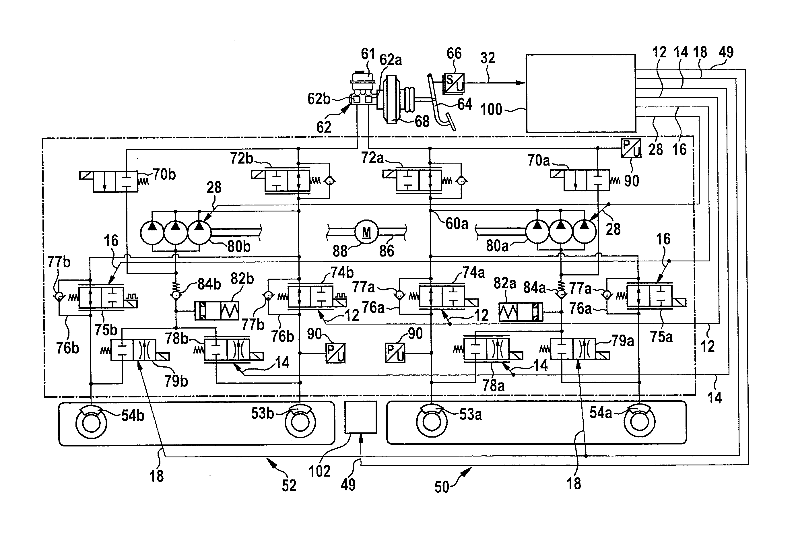
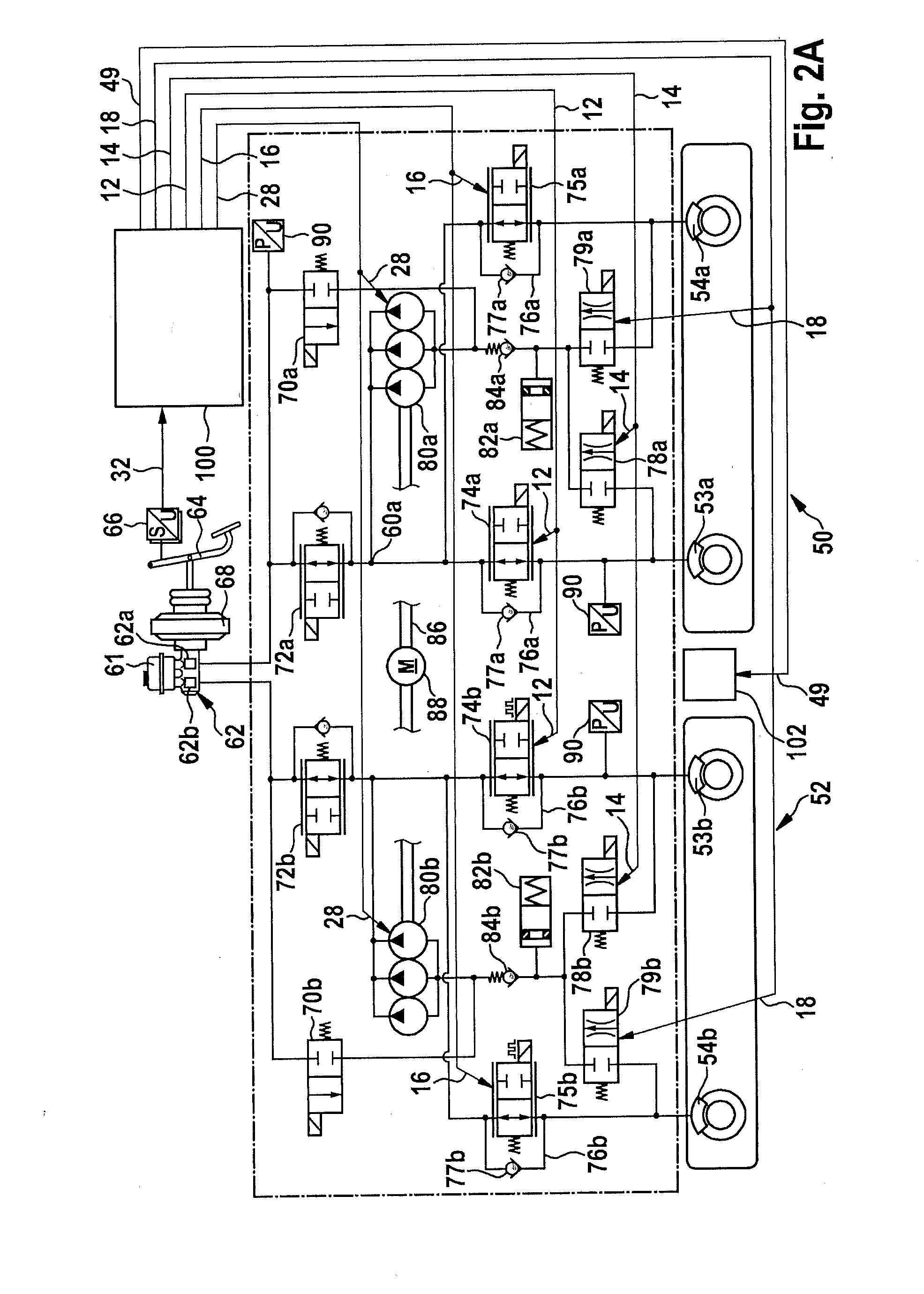
[0015]The control device shown schematically in FIG. 1 is designed for the controlling of components of a brake system (not shown) of a vehicle. The possible design of the components of the brake system is described in more detail in relation to the following Figures.

[0016]The control device has a controller 10 by which the brake system can be controlled (at least) to a first operating mode in which, when a driver actuates a brake actuating element situated on the brake system, a buildup of brake pressure is (substantially) prevented at least in a first wheel brake caliper of a first brake circuit of the brake system. This can also be described by saying that despite an actuation strength not equal to zero of the actuation of the brake actuating element, a buildup of brake pressure is (substantially) prevented at least in the first wheel brake caliper of the first brake circuit of the brake ...


PUM


Abstract

In a control device for a brake system of a vehicle, given an actuation of a brake actuating element, a buildup of brake pressure is prevented at least in a first wheel brake caliper of a first brake circuit, a first wheel inlet valve of the first wheel brake caliper being controlled to a partly open state, and a first wheel outlet valve of the first wheel brake caliper being kept in a partly open state, a second wheel inlet valve of a second wheel brake caliper of the first brake circuit being controlled to a partly open state, and a second wheel outlet valve of the second wheel brake caliper being controlled to a closed state, in such a way that a brake pressure can be built up in the second wheel brake caliper.

Description

BACKGROUND OF THE INVENTION[0001]1. Field of the Invention[0002]The present invention relates to a control device for a brake system of a vehicle. The present invention also relates to a brake system for a vehicle. In addition, the present invention relates to a method for operating a brake system of a vehicle and to a method for operating a brake system of a vehicle having a diagonal brake circuit configuration.[0003]2. Description of the Related Art[0004]In published German patent application document DE 196 04 134 A1, a method and a device are described for controlling a brake system of a motor vehicle having an electric drive. When the vehicle is braked using the electric drive for the simultaneous charging of a battery, the hydraulic braking moment exerted on at least one wheel by the at least one wheel brake cylinder of the hydraulic brake system is to be reduced / deactivated despite an actuation of the brake pedal. For this purpose, the pressure medium displaced from the maste...

Claims


Application Information

Patent Timeline
Patent Type & Authority Applications(United States)
IPC IPC(8): B60T8/26
CPCB60T8/266B60T1/10B60T7/042B60T7/12B60T8/1755B60T8/17616B60T8/268B60T8/326B60T8/341B60T8/3655B60T8/4081B60T8/4275B60T8/4872B60T13/146B60T13/662B60T13/686B60T13/74B60T2220/04B60T2270/604B60W10/184B60W10/188B60W10/192B60W30/18127B60Y2300/89
Inventor STRENGERT, STEFANKUNZ, MICHAELMAUCHER, THORSTEN
Owner ROBERT BOSCH GMBH
Why Eureka
Try Eureka