
Valve device and method for transferring a transfer medium

a valve device and transfer medium technology, applied in the direction of manufacturing tools, solvent machines, other domestic articles, etc., can solve the problems of contaminating the environment of said media, unable to breathe in diatomite dust, and difficult to prevent diatomite dust development or release into the environment, so as to avoid unwanted contamination of the environment in a simple and secure manner

Active Publication Date: 2014-09-04
SARTORIUS STEDIM BIOTECH GMBH
View PDF2 Cites 14 Cited by
  • Summary
  • Abstract
  • Description
  • Claims
  • Application Information

AI Technical Summary

Benefits of technology

The valve device described in this patent allows for easy and secure connection of containers without the need for expensive rinsing operations. The valve disks are designed to abut against each other without contaminating the transfer medium. The valve can be latched or locked to prevent unintentional opening and additional rinses are not necessary as there is no space to be rinsed between the valve disks. The design is simple and cost-efficient and can be used as a single-use product. The actuating part and the form attachment can be easily detached from each other to prevent unwanted movement. The valve disks can be easily latched together without the need for a complex latching mechanism.

Problems solved by technology

Insofar as transfer media contained in a first container are to be transferred into a separate second container, the problem of preventing said media contaminating the environment frequently arises.
As this, however, is only applicable for dry dust like particle forms, it is necessary when working with such filtering aids to take preventive technological measures which, to the greatest possible extent, prevent the development or the release of diatomite dust into the environment and make breathing it in completely impossible.
In this case, it is disadvantageous that the two valves are connected together by means of a connecting arrangement which comprises an intermediate space.
Here too, it is disadvantageous that in the open state the valve plates are in each case contaminated from their two sides.
Such a two-way valve for the transfer of hot exhaust gas flows in exhaust gas installations is also not designed for the transfer of particulate transfer media avoiding the development of dust.

Method used


Image

  • Valve device and method for transferring a transfer medium
  • Valve device and method for transferring a transfer medium
  • Valve device and method for transferring a transfer medium

Examples


Embodiment Construction

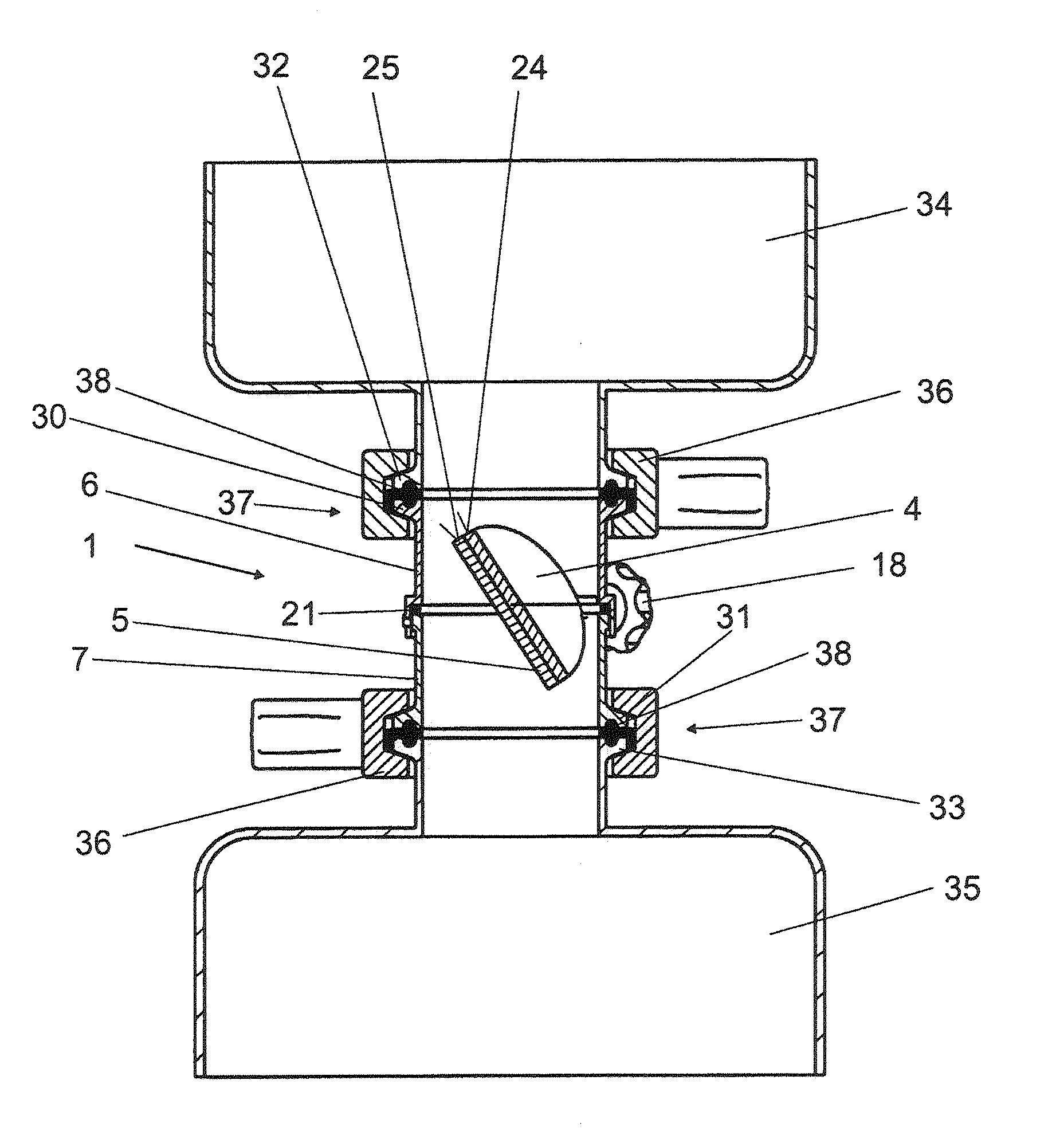
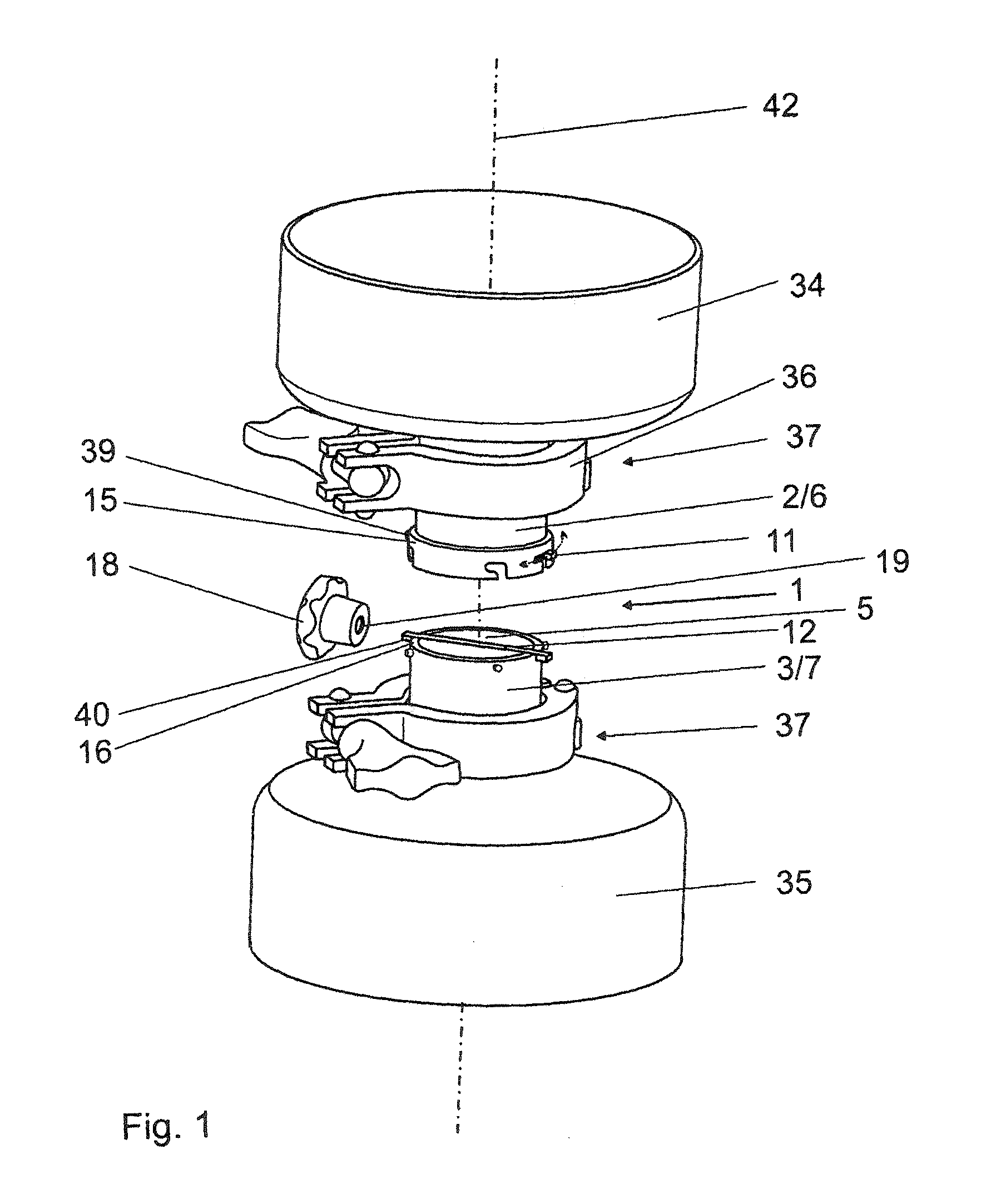
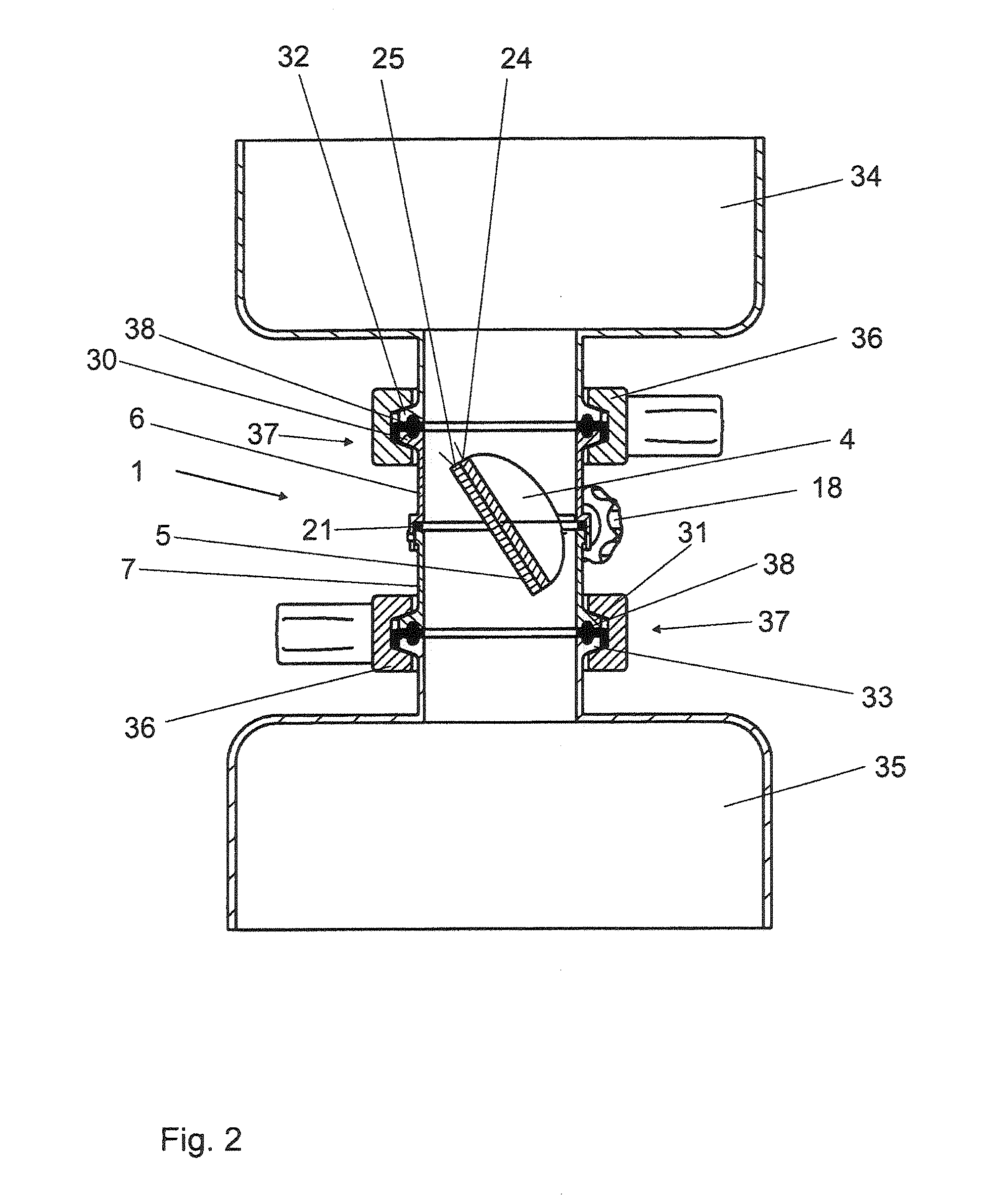
[0050]A valve device 1 consists substantially of an inflow 2, an outflow 3 and two valve disks 4, 5 which are arranged one behind another in the direction of flow.

[0051]The inflow 2 is formed by a first housing section 6. The outflow 3 is formed by a second housing section 7.

[0052]The two housing sections 6, 7 are lockable together at their ends 8, 9 which face one another by means of at least one locking means 10 (four locking means 10 in the exemplary embodiment of FIG. 1) which can be realized as a bayonet closure. The first housing section 6 comprises the first valve disk 4 at its end 8. The second housing section 7 comprises the second valve disk 5 on its end 9. The first valve disk 4 comprises a half-shaft 11 which is fixedly connected thereto and by way of which it is mounted so as to be pivotable in the end 8. In a corresponding manner, the second valve disk 5 comprises a second half-shaft 12, by way of which it is mounted so as to be pivotable in the end 9.

[0053]With the ho...


PUM


Abstract

The invention relates to a valve device and to a method for transferring a transfer medium, said valve device and method having an inflow, an outflow and two valve disks which are arranged one behind another in the direction of flow and are pivotable about a common rotational axis for opening and closing the lumen which surrounds them, wherein the inflow and the outflow are formed by two housing sections which are lockable together, the ends of which facing one another receive in each case a valve disk with a fixedly connected half-shaft, wherein, with the housing sections in the locked state, the two half-shafts form one common shaft which is pivotable about the rotational axis and the valve disks abut closely against one another, and wherein, with the housing sections in the non-locked state, the valve disks in each case close the lumen of the housing section receiving them.

Description

BACKGROUND[0001]1. Field of the Invention[0002]The invention relates to a valve device for transferring a transfer medium, said valve device having an inflow, an outflow and two valve disks which are arranged one behind another in the direction of flow and are pivotable about a common rotational axis for opening and closing the lumen which surrounds them.[0003]2. Description of the Related Art[0004]The invention also relates to a method for transferring a transfer medium using a valve device, the inflow of which is connected to a first container which contains the transfer medium and the outflow of which is connected to a second container which receives the transfer medium.[0005]Insofar as transfer media contained in a first container are to be transferred into a separate second container, the problem of preventing said media contaminating the environment frequently arises. Thus, for example, a powdery filtering aid (diatomite / diatomaceous earth), which is transferred as a transfer ...

Claims


Application Information

Patent Timeline
IPC IPC(8): F16K1/22
CPCF16K1/22F16K1/222F16K1/223B65G69/183Y10T29/49405Y10T137/87941
Inventor DIEL, BERNHARD
Owner SARTORIUS STEDIM BIOTECH GMBH
Learn More