Power distribution rack bus bar assembly and method of assembling the same

a technology for power distribution racks and bus bars, which is applied in the construction details of electrical apparatus, substation/switching arrangement casings, printed circuit board receptacles, etc. it can solve the problems of increasing the amount of emi, complex network of wires and cables within a limited space, and multiple layers of expensive insulation

Active Publication Date: 2014-09-04
ABB (SCHWEIZ) AG
View PDF16 Cites 31 Cited by
  • Summary
  • Abstract
  • Description
  • Claims
  • Application Information

AI Technical Summary

Problems solved by technology

Further, industry regulations require a minimum amount of spacing between AC and DC cables that often results in multiple layers of expensive insulation per cable to ensure AC/DC isolation while minimizing the effect of electromagnetic interference (EMI) between the AC connections and DC connections.
However, such a design results in a complex network of wires and cables within a limited amount of space.
A...

Method used


Image

  • Power distribution rack bus bar assembly and method of assembling the same
  • Power distribution rack bus bar assembly and method of assembling the same
  • Power distribution rack bus bar assembly and method of assembling the same

Examples


Embodiment Construction

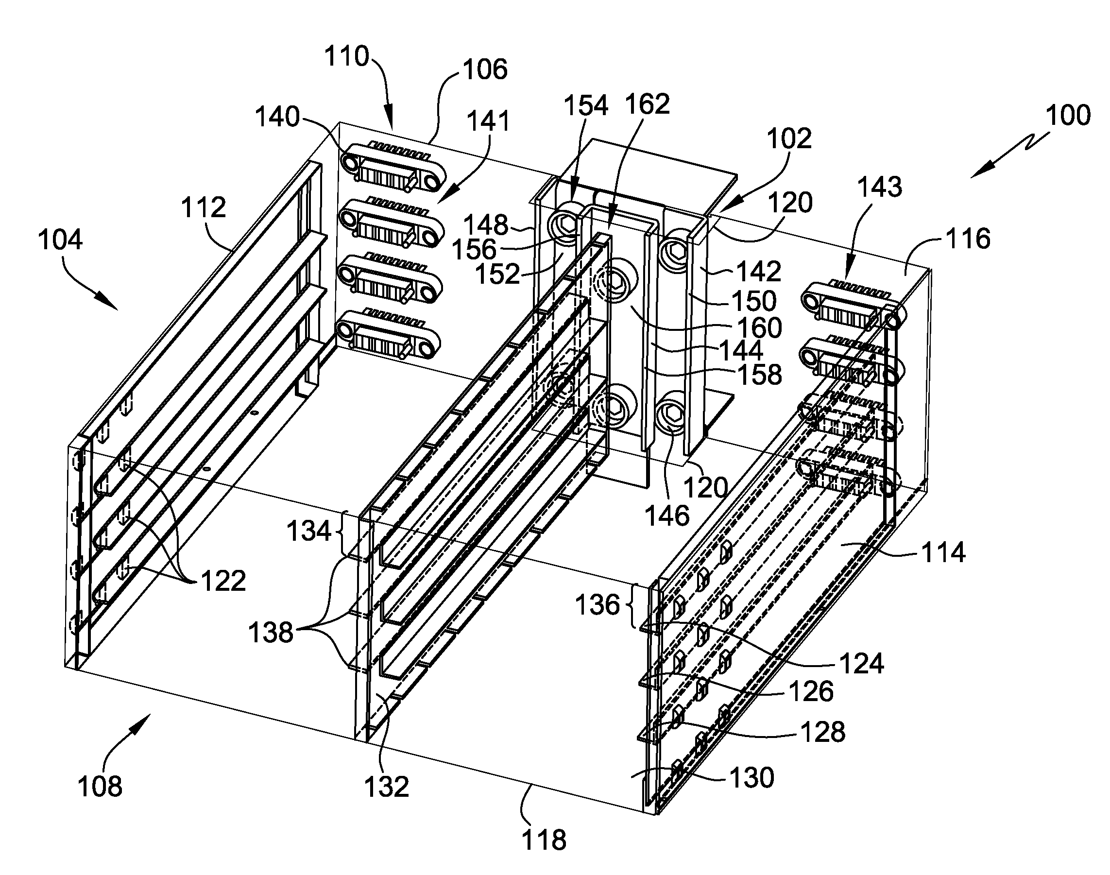
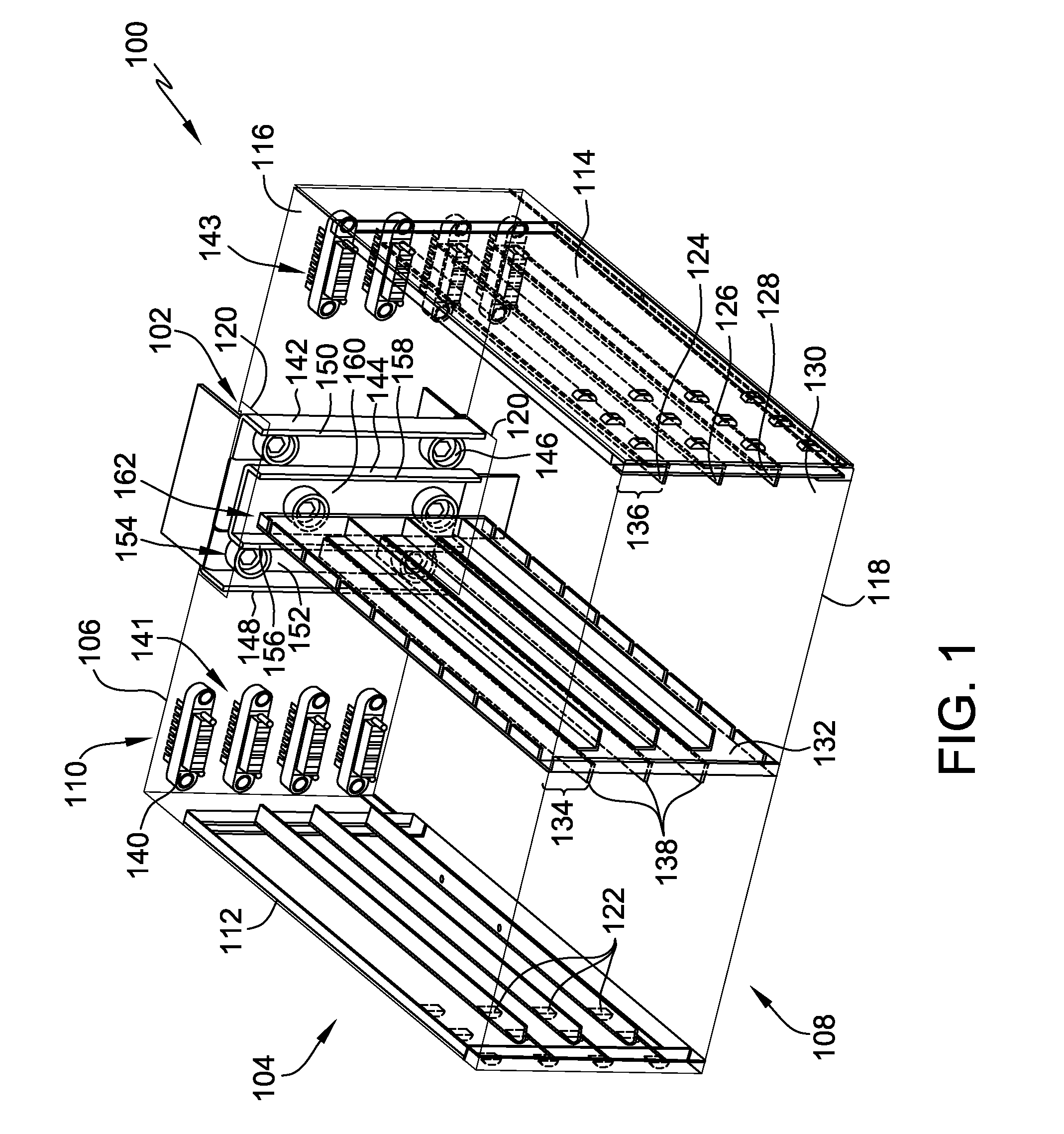
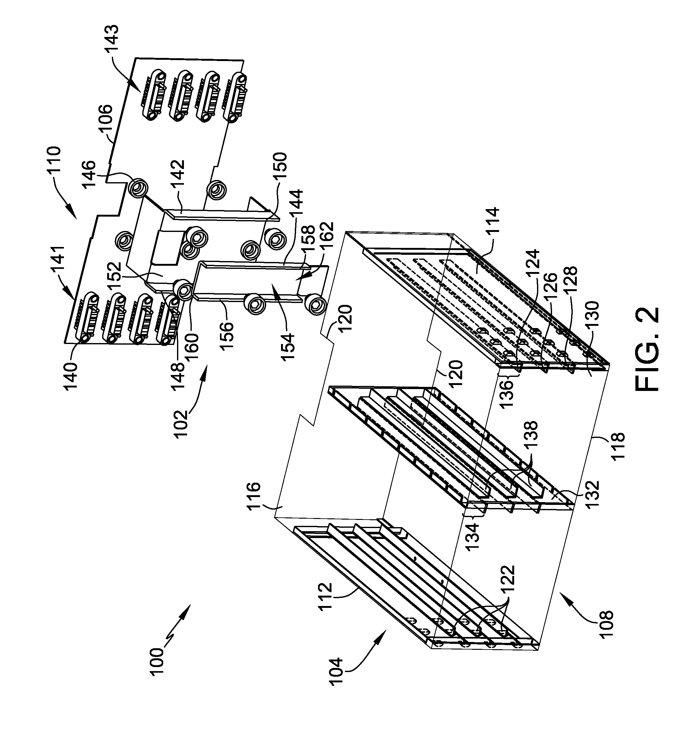
[0014]The embodiments include a new power distribution rack that defines a plurality of shelves, each having adjacent left and right slots. The rack includes a plurality of electronics modules that are inserted into the slots and are coupled to a centrally-positioned bus bar assembly. The bus bar assembly includes nested inner and outer bus bars that are coupled directly to AC and DC connectors of the electronics modules to eliminate the need for a backplane and intermediate connectors. Orientation of the electronics modules facilitate positioning the DC connectors on the module in the left slot adjacent DC connectors of the module in the right slot such that the central bus bar assembly is directly coupled to each DC connector. Such a configuration simplifies the cable networking and maximizes usage of the limited allowable space within the power distribution rack to meet industry regulations and provide superior performance, reduced costs and easy use.

[0015]FIG. 1 illustrates a pe...


PUM

PropertyMeasurementUnit
Angleaaaaaaaaaa
Distanceaaaaaaaaaa
Distributionaaaaaaaaaa

Abstract

A power distribution rack includes a chassis that defines a first slot and a second slot adjacent the first slot. The power distribution rack also includes a plurality of electronics modules including a first module coupled within the first slot and a second module coupled within the second slot. A central bus bar assembly is coupled to the chassis and includes an outer bus bar including a first flange, a second flange, and a first bus plate extending therebetween. The first and second flanges and the first bus plate define a first channel. The bus bar assembly further includes an inner bus bar coupled within the first channel. The inner bus bar includes a third flange, a fourth flange, and a second bus plate extending therebetween. The first and third flanges are coupled to the first module and the second and fourth flanges are coupled to the second module.

Description

CROSS REFERENCE TO RELATED APPLICATIONS[0001]This application claims priority to and the benefit of the filing date of U.S. Provisional Application No. 61 / 771,936 filed on Mar. 3, 2013, which is hereby incorporated by reference in its entirety.BACKGROUND[0002]The embodiments described herein relate generally to a power distribution rack, and, more specifically, to a central bus bar assembly for a power distribution rack and methods of assembly thereof.[0003]Electrical components or modules are sometimes stored in a stacked relationship not only to allow the modules to be electrically interconnected with one another, but also so they can be readily accessed and used. This is particularly true in power management situations in which a large number of densely packed individual modules are typically mounted together in a rack system to create a desired power management system. Such rack systems may consist of a frame structure including layered shelves that define individual slots into ...

Claims


Application Information

Patent Timeline
IPC IPC(8): H02G5/04H05K13/04
CPCH05K13/04H02G5/04Y10T29/49117H05K7/14325H05K7/14329H05K7/1432
Inventor STEEVES, MICHAEL CLYDENGUYEN, KHANH QUOCNESSMAN, PAUL SCOTTREDDY, RAGHOTHAMA
Owner ABB (SCHWEIZ) AG
Why Eureka
Try Eureka