

Energy Recovery Apparatus for a Refrigeration System
- Summary
- Abstract
- Description
- Claims
- Application Information
AI Technical Summary
Benefits of technology
Problems solved by technology
Method used
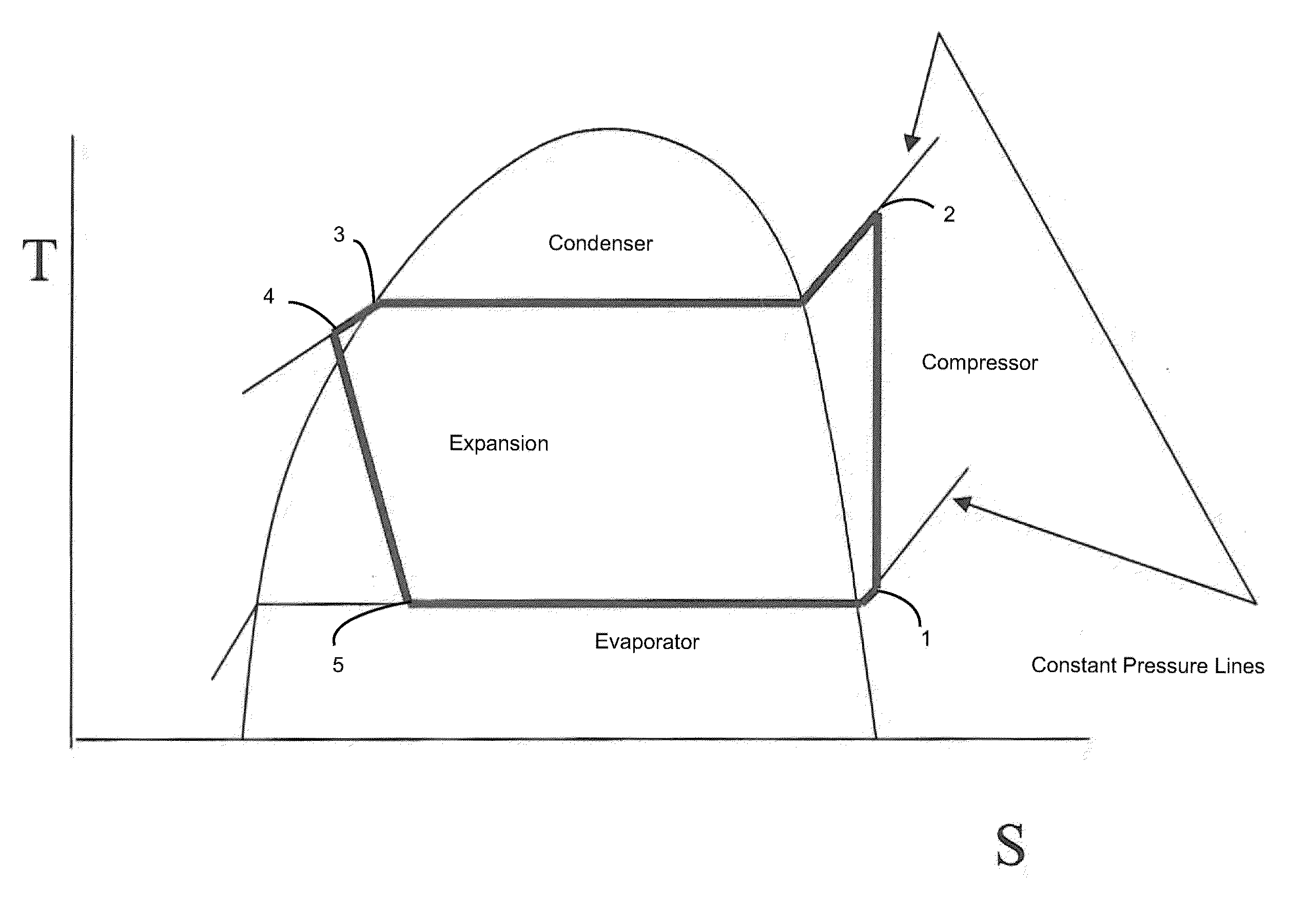
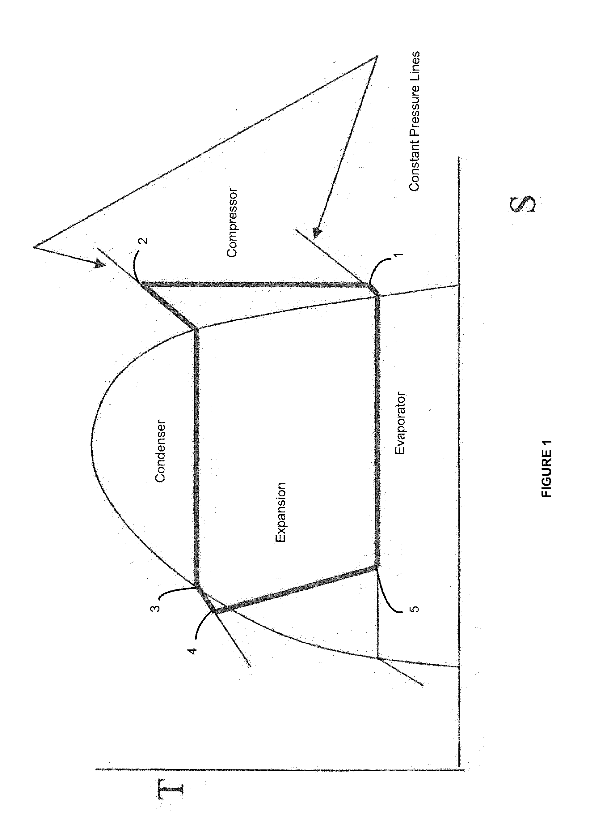
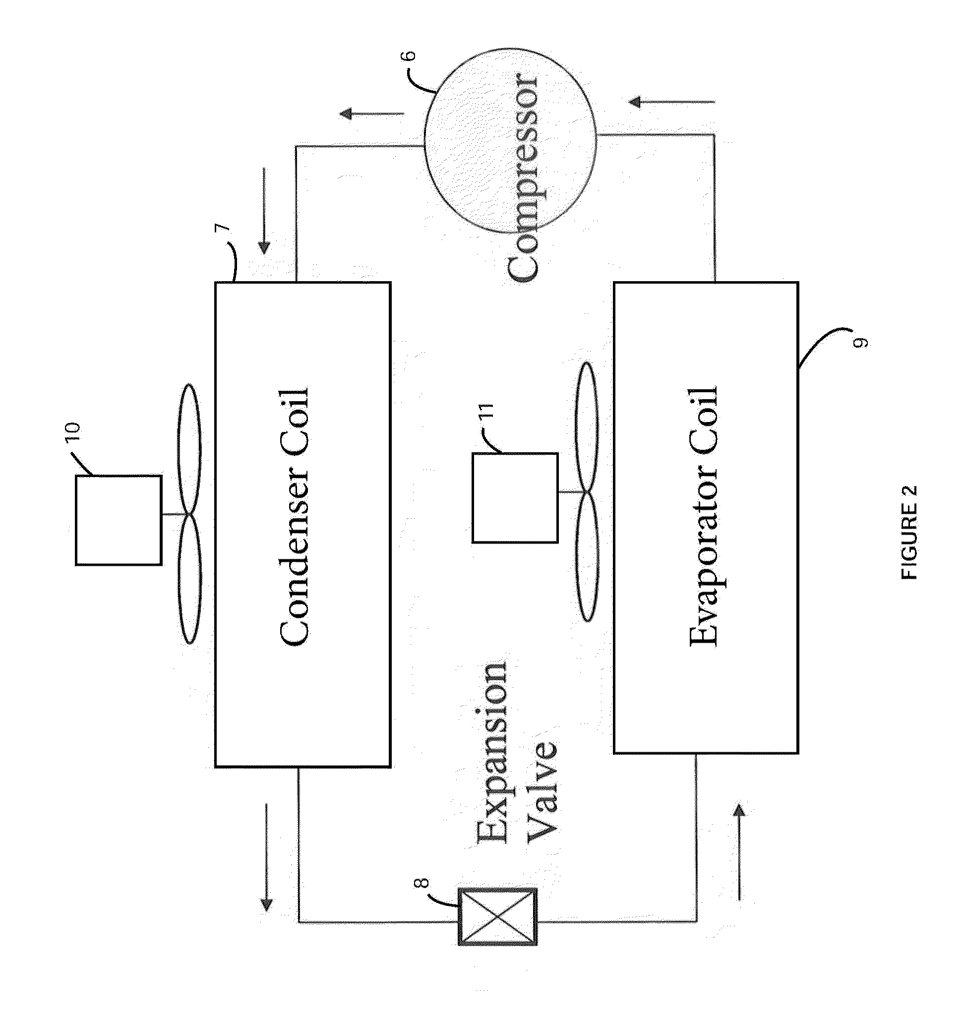
Image

Examples
Embodiment Construction
[0047]An embodiment of an energy recovery apparatus of the present invention is indicated generally by reference numeral 14 in FIGS. 5-9. The energy recovery apparatus 14 is basically comprised of a housing 16, a turbine 18 and a generator 20. The turbine 18 and generator 20 are preferably contained in the housing.
[0048]The housing 16 is preferably comprised of three parts. A first, lower center housing part 22 has an interior that supports a bearing assembly 24. The center part 22 is attached to a second, side wall part 26 of the housing. The side wall 26 is preferably generally cylindrical in shape and extends around an interior volume of the housing 16. The center housing part 22 also includes a hollow center column 28. The interior of the center column 28 supports a second bearing assembly 30. A third, cover part of the housing 32 is attached to the top of the side wall 26. The cover part 32 encloses the hollow interior of the housing 16. The center housing part 22 preferably ha...
PUM
| Property | Measurement | Unit |
|---|---|---|
| Fraction | aaaaa | aaaaa |
| Fraction | aaaaa | aaaaa |
| Speed | aaaaa | aaaaa |
Abstract
Description
Claims
Application Information