Engine Exhaust Extractor With Internal Airfoils and Method of Manufacturing

Active Publication Date: 2018-08-16
EXHAUST THRUSTER LLC
View PDF0 Cites 0 Cited by
  • Summary
  • Abstract
  • Description
  • Claims
  • Application Information

AI Technical Summary

Benefits of technology

The present invention is an improved engine exhaust extractor that improves the performance and efficiency of internal combustion engines. It includes a coaxial inner and outer tubes with helically oriented vanes and reliefs to allow gases to flow between them. The inner tube is held in place by end pieces that also have a fan-like structure to increase the velocity of exhaust gases flowing through it. The exhaust extractor is constructed from only six parts and requires only two welds. Its technical effects include improved engine performance, efficiency, reduced emissions, increased power output, and improved fuel economy.

Problems solved by technology

However, meeting federally mandated mileage requirements remains a challenge, and further improvements are necessary.
Pollution levels in metropolitan areas remain unacceptably high at times, and create an immediate direct health issue for humans, and a longer term issue due to the damage to plant life.
Automotive based pollution remains an issue, and auto makers are continually challenged to reduce the emissions from new automobiles.
But while the intake aspect of engine design has advanced drastically, exhaust systems have not similarly advanced.
Unfortunately, the exhaust extractor disclosed in the '500 patent is somewhat complex and expensive to manufacture.

Method used


Image

  • Engine Exhaust Extractor With Internal Airfoils and Method of Manufacturing
  • Engine Exhaust Extractor With Internal Airfoils and Method of Manufacturing
  • Engine Exhaust Extractor With Internal Airfoils and Method of Manufacturing

Examples


Embodiment Construction

[0034]The following description is of the best mode presently contemplated for carrying out the invention. This description is not to be taken in a limiting sense, but is made merely for the purpose of describing one or more preferred embodiments of the invention. The scope of the invention should be determined with reference to the claims.

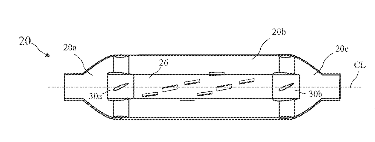
[0035]Several elements of the exhaust extractor are described herein as having a wing shape or a wing shaped cross-section. The term “wing” is used herein to describe a shape with a somewhat blunt or rounded leading edge, a thickest point closer to the leading edge than a trailing edge, and tapering from the thickest point to the trailing edge. The leading edge is not necessarily rounded, but is less pointed than the trailing edge.

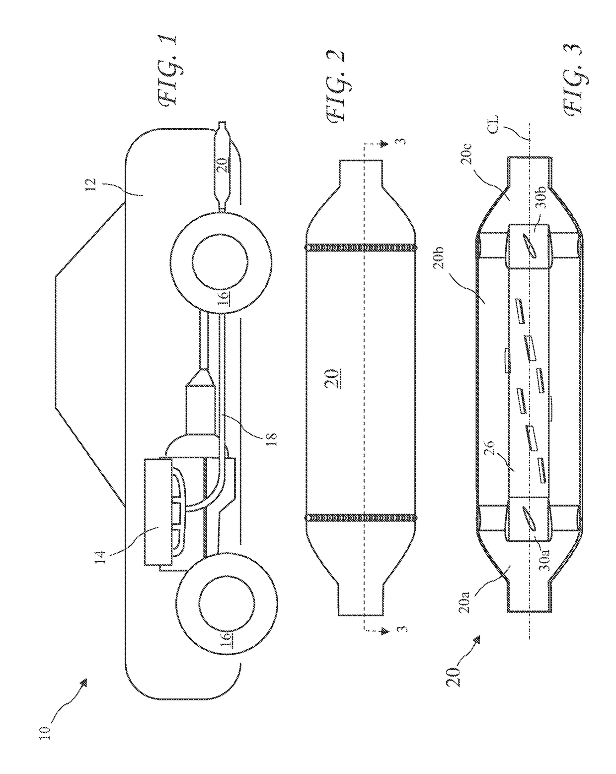
[0036]A vehicle 10 including a body 12, an engine 14, and wheels 16 is shown in FIG. 1. The engine 14 consumes fuel and produces exhaust which passes through an exhaust pipe 18 and exits the vehicle through an improved e...


PUM


Abstract

An improved engine exhaust extractor improves internal combustion engine performance and efficiency. The exhaust extractor includes coaxial inner and outer tubes separating a flow into an inner flow inside the inner tube and an outer flow between the tubes and merging near the exhaust extractor outlet. Helically oriented vanes extend radially from an outer face of the inner tube and reliefs are cut into the inner tube to allow gasses to flow to the outer flow. The inner tube is held in place by end pieces connecting the inner tube to the outer tube. The end pieces include fan blades with wing shaped cross-sections to increase the velocity of exhaust gasses flowing through the exhaust extractor. The fan-like supports and helically oriented vanes cause the outer flow to rotate about a central axis. The exhaust extractor is constructed from only six parts requiring only two welds.

Description

BACKGROUND OF THE INVENTION[0001]The present invention relates to improving the efficiency of internal combustion engines, and in particular to an exhaust system which aids in extracting exhaust gases from the combustion chamber.[0002]There is a continuing desire to improve the performance, efficiency, and environmental friendliness of internal combustion engines. Cars, motorcycles, and event trucks are raced every weekend in the United States. Even a small increase in power can provide a dramatic advantage in racing. The efficiency of exhaust systems is known to be a critical aspect of engine performance, and attempts to improve exhaust systems to unlock power have been ongoing for many years.[0003]Increasing energy costs have also motivated manufactures to continually seek to improve vehicle mileage, both to gain market share, and to satisfy government mileage requirements. Improvements to exhaust systems in the form of reduced restriction and tuned lengths have become common plac...

Claims


Application Information

Patent Timeline
IPC IPC(8): F01N13/08F04D19/00F04D25/16
CPCF01N13/08F04D19/002F04D25/166F01N2450/22F01N2290/06F01N2470/08F01N2260/06F01N13/082F01N2290/04F01N2470/24F02B27/04Y02T10/12F01N1/12
Inventor MARTINEZ, ROY R.
Owner EXHAUST THRUSTER LLC
Why Eureka
Try Eureka