Stand for electronic apparatus

a technology for electronic devices and stands, applied in the direction of stand/trestles, kitchen equipment, support structure mounting, etc., to achieve the effects of convenient lifting of cutout portions, high usability, and convenient carrying

Active Publication Date: 2014-09-18
WACOM CO LTD
View PDF7 Cites 13 Cited by
  • Summary
  • Abstract
  • Description
  • Claims
  • Application Information

AI Technical Summary

Benefits of technology

[0034]In the present invention configured as described above, the cutout portion provided in the inner periphery of the outer peripheral portion of the base section is provided at a position corresponding to the first lock section of the first leg section when the first leg section is rotated to the folded position. Thus, when the user makes an attempt to move a leg section to a support position from a folded position, the user may insert a finger into the finger insertion cutout portion and easily raise the cutout portion by merely picking the cutout portion in order to erect the leg section on the base section. As a result, the present invention provides the electronic apparatus with a high degree of usability.
[0035]In accordance with the stand for an electronic apparatus provided by the present invention according to various embodiments, the apparatus is easy to carry even when the stand is attached to the apparatus. When the electronic apparatus is used in an obliquely erected state on a table, the inclination angle of the main body of the electronic apparatus with respect to the table can be easily changed. As a result, the present invention provides the electronic apparatus with a high degree of usability.

Problems solved by technology

In such cases, in the conventional tilt unit described above, the user has to go to all the trouble to remove the tilt unit from the main body of the electronic apparatus.

Method used


Image

  • Stand for electronic apparatus
  • Stand for electronic apparatus
  • Stand for electronic apparatus

Examples


Embodiment Construction

[0051]Stands according to embodiments of the present invention are explained below in reference to accompanying drawings.

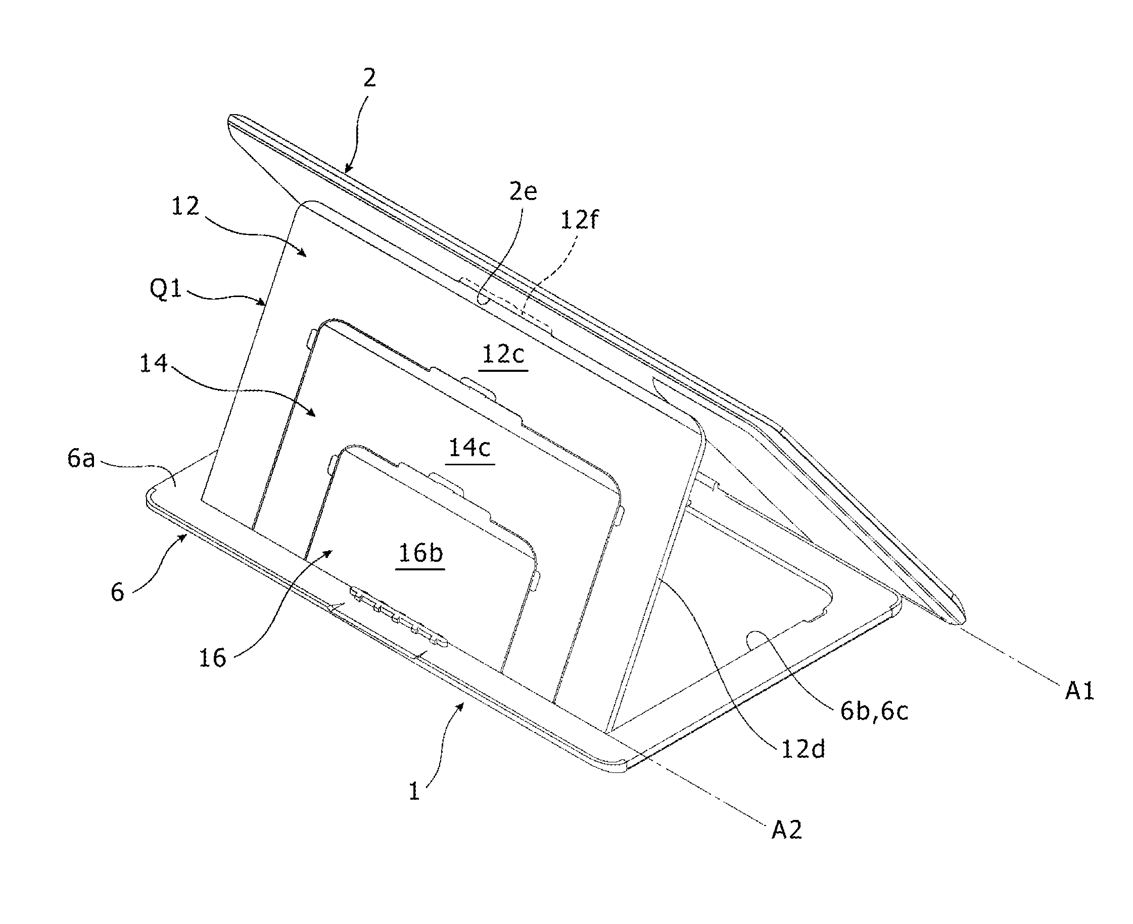
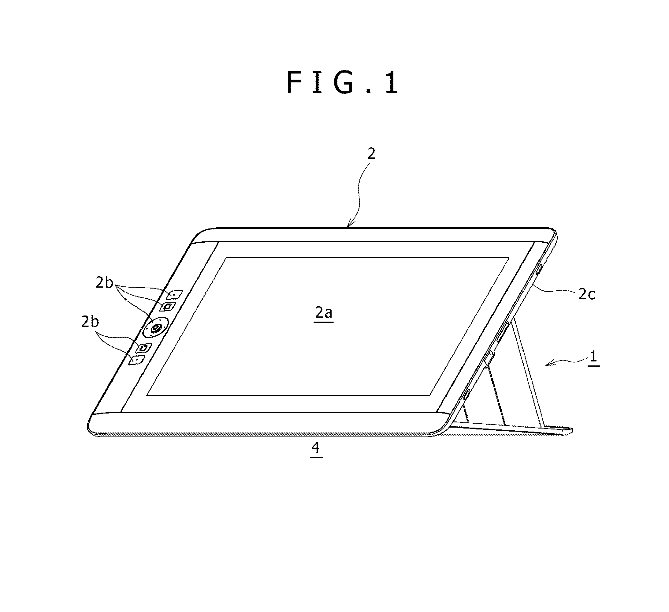
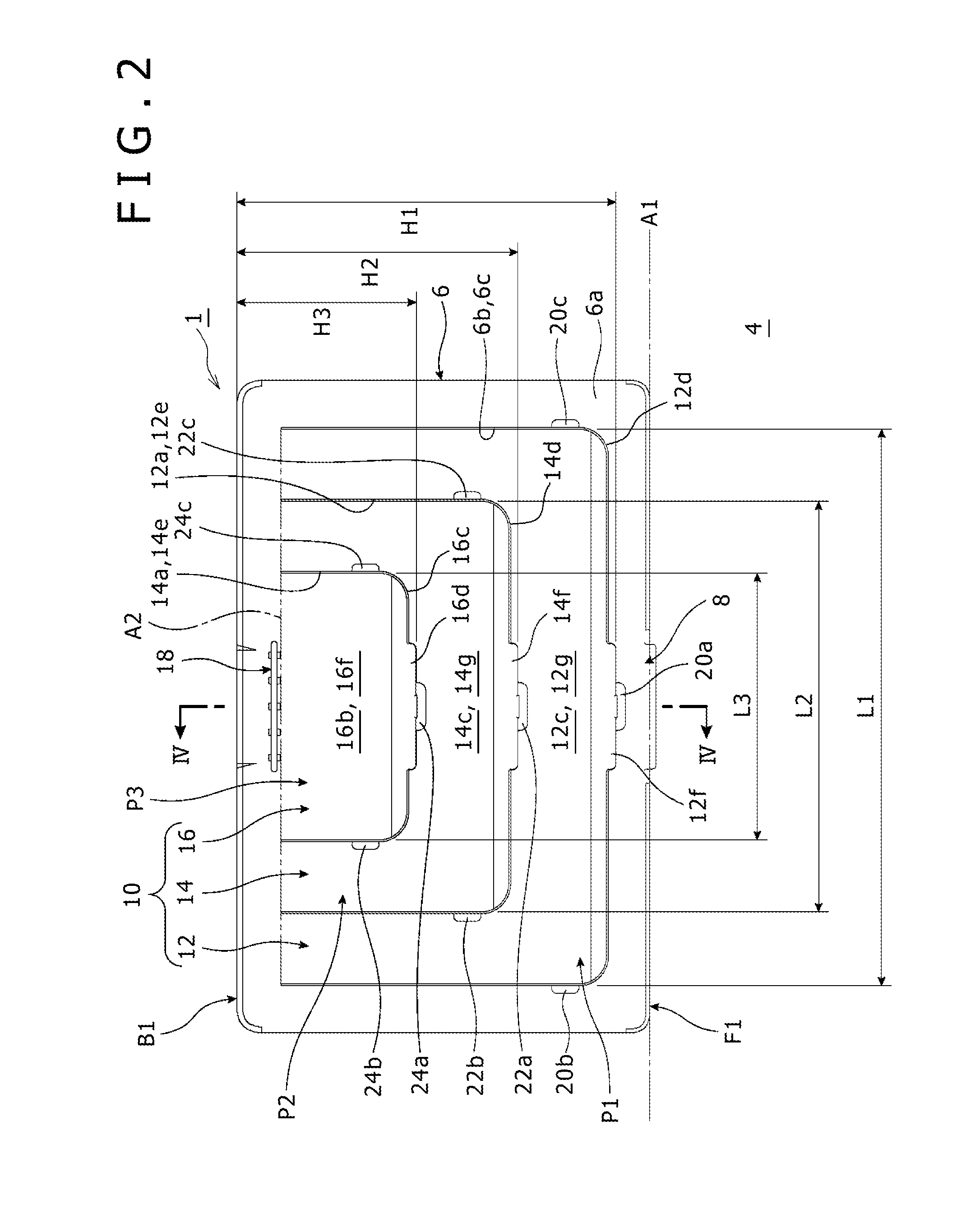
[0052]FIG. 1 is a schematic perspective view showing a state, in which a stand 1 according to an embodiment of the present invention supports a tablet-terminal main body 2 from a rear side of the main body, as seen obliquely from a front side of the main body. FIG. 2 is a top view of the stand 1 according to the embodiment of the present invention.

[0053]As shown in FIGS. 1 and 2, the stand 1 according to the embodiment of the present invention supports the rear side of the tablet-terminal main body 2 serving as an electronic apparatus in such a way that the tablet-terminal main body 2 is obliquely erected on an upper surface 4 of a table. The stand 1 includes a base section 6, which has a plate shape and is placed on the upper surface 4 of the table.

[0054]A liquid-crystal display section 2a having a rectangular shape is provided at the center of the surface of the...


PUM


Abstract

A stand for an electronic apparatus is provided, which is configured to support a rear surface of the electronic apparatus at different inclining heights. The stand includes a base section composed of a plate member having a first edge and a second edge, and the plate member is configured to rotationally support the electronic apparatus adjacent to the first edge and defines an area for facing the rear surface of the electronic apparatus. The area defines a plurality of leg sections of different sizes, each including a lock section configured to lock with the rear surface of the electronic apparatus and a support section provided adjacent to the second edge of the plate member to serve as a rotational support for the leg section relative to the plate member. The support sections that serve as rotational supports for the plurality of leg sections share a common rotational axis.

Description

BACKGROUND[0001]1. Technical Field[0002]The present invention relates to a stand for an electronic apparatus. More particularly, the present invention relates to a stand configured to be provided on the rear-surface side of an electronic apparatus to serve as a stand for the apparatus and used to change the orientation of the apparatus.[0003]2. Description of the Related Art[0004]In the past, a support stand was provided on the rear side of the main body of an electronic apparatus to obliquely erect the main body of the apparatus on a table as described, for example, in a document such as Japanese Patent Laid-open No. 2008-115925. As described in the document, on the front surface of the main body of the electronic apparatus, a display section and a display operation section are provided, whereas a tilt unit is provided on the rear surface of the main body of the electronic apparatus. The tilt unit is used to support the main body of the electronic apparatus at an inclination angle ...

Claims


Application Information

Patent Timeline
Patent Type & Authority Applications(United States)
IPC IPC(8): H05K7/16
CPCH05K7/16F16M11/10F16M11/38F16M13/00F16M2200/08A47B23/043F16M2200/024
Inventor HUEBNER, VOLKER
Owner WACOM CO LTD
Why Eureka
Try Eureka