Bulb socket having terminals connected to a partially stripped cord

a technology of terminals and plug-in sockets, which is applied in the direction of lighting support devices, coupling device connections, lighting and heating apparatuses, etc., can solve the problems of shortening of lamp strings and certainly not perfect arrangements, and achieve the effect of eliminating the potential risk of power cord breaking and eliminating the potential risk of power cord piercing

Inactive Publication Date: 2014-09-18
LIN DE HUI
View PDF10 Cites 1 Cited by
  • Summary
  • Abstract
  • Description
  • Claims
  • Application Information

AI Technical Summary

Benefits of technology

[0003]To overcome the drawback of the conventional way of connecting an illuminant received and retained in a socket of a lamp string with a power cord, the present invention replaces the connection engagement realized with knife-like sharp pins piercing through the power cord by secured direct contact engagement established between terminals of an LED and the conductive cores of a partially stripped power cord for the purposes of eliminating the potential risk of power cord breaking.
[0004]To achieve the above object, the present invention provides a connection seat of bulb socket of decorative lamp string, which comprises a main body comprising an upper portion and a bottom portion both having a hollow interior. The top portion comprises a centrally located the partition board on which an LED is seated with two terminals of the LED on opposite sides of the partition board. A cover is mounted to the top portion. The bottom portion comprises a centrally located partition board and two stop boards on two sides and having inside inclination surfaces. The terminals of the LED are arranged to extend into the bottom portion and positioned against the partition board of the bottom portion. The power cord comprises two partially stripped core conductors that are respectively received between the partition board and the stop boards of the bottom portion and are respectively set in engagement with the two terminals of the LED. A bottom cap comprises two raised bars and is mounted to the bottom portion in such a way that the two raised bars push the two core conductors in such a direction to have the core conductors and the terminals of the LED securely fixed between the partition board and the stop boards of the bottom portion. In this way, the power cord can be set in connection with the illuminant without applying the conventionally used piercing engagement, whereby the potential risk of breaking the power cord due to piercing can be eliminated.

Problems solved by technology

However, electrical connection established with such piercing engagement may lead to undesired breaking and thus detachment of the power cord and consequently shorting of the lamp string may result.
This is certainly not a perfect arrangement and further improvement is needed.

Method used


Image

  • Bulb socket having terminals connected to a partially stripped cord
  • Bulb socket having terminals connected to a partially stripped cord
  • Bulb socket having terminals connected to a partially stripped cord

Examples


Embodiment Construction

[0011]The following descriptions are exemplary embodiments only, and are not intended to limit the scope, applicability or configuration of the invention in any way. Rather, the following description provides a convenient illustration for implementing exemplary embodiments of the invention. Various changes to the described embodiments may be made in the function and arrangement of the elements described without departing from the scope of the invention as set forth in the appended claims.

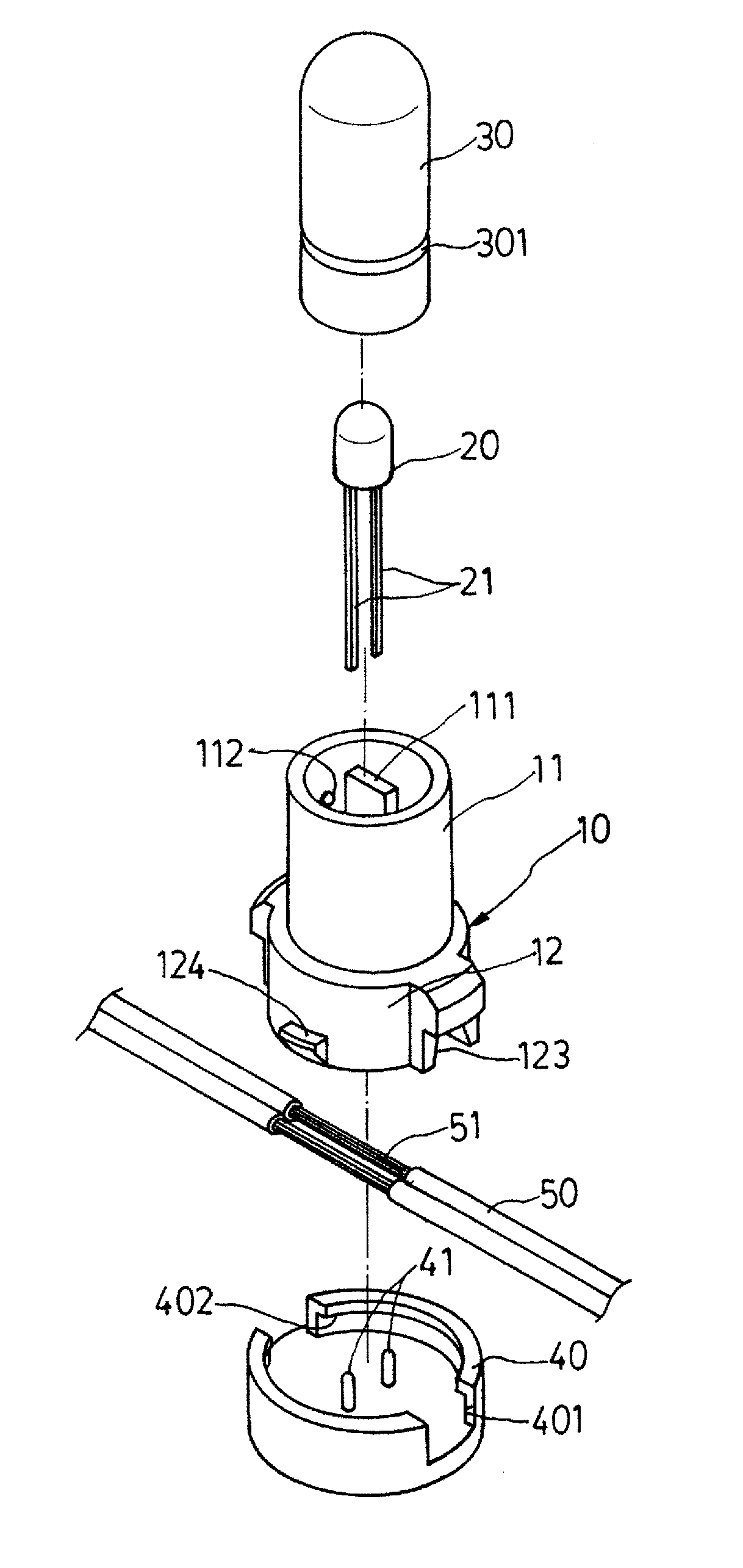
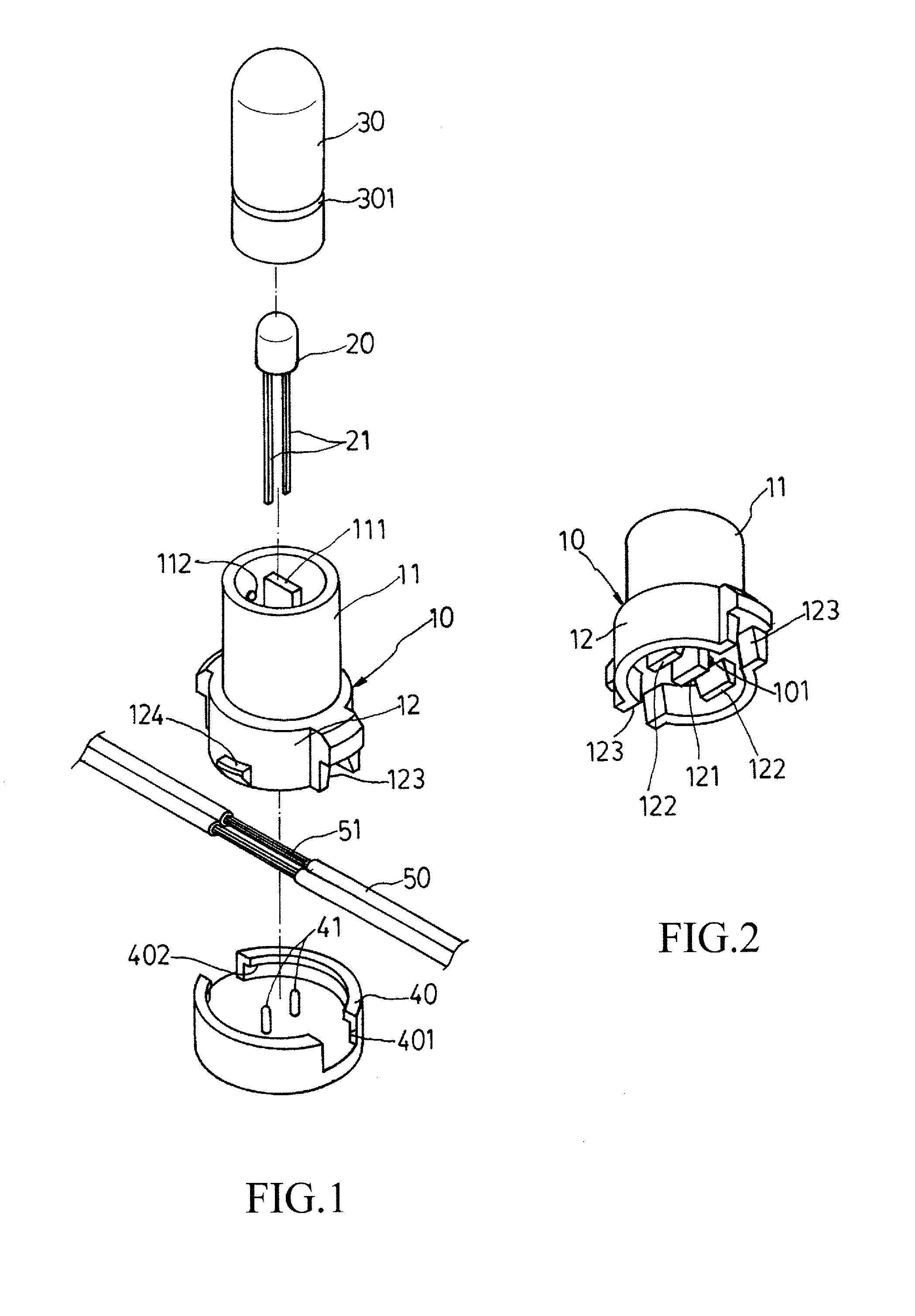
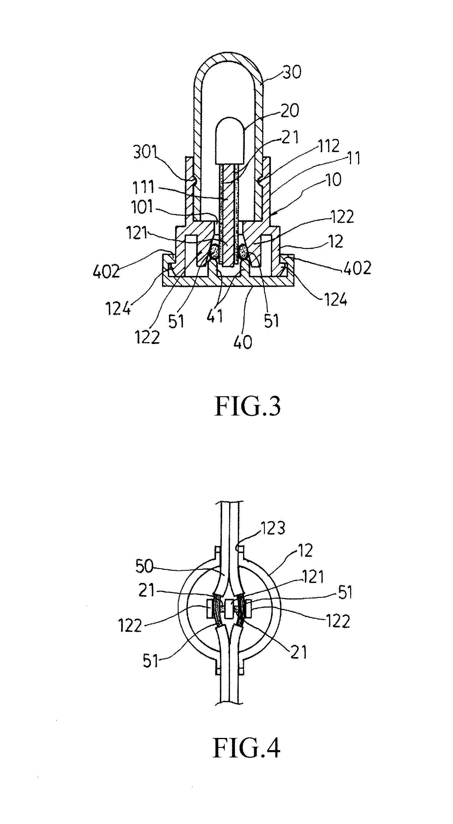
[0012]Referring to FIGS. 1-4, the present invention provides a connection seat of bulb socket of decorative lamp string, which is composed of a main body (10), a light-emitting diode (LED) (20), a cover (30), a bottom cap (40), and a power cord (50). The main body (10) comprises a top portion (11) and a bottom portion (12), each defining a hollow interior. The top portion (11) receives a partition board (111) arranged centrally in the interior thereof and mounted to an internal wall between the top ...


PUM


Abstract

A connection seat of bulb socket of decorative lamp string includes a main body having upper and bottom portions. The top portion includes a partition board on which an LED is seated with two terminals on opposite sides of the partition board. The bottom portion has a partition board and two stop boards having inside inclination surfaces. The terminals of the LED are arranged to extend into the bottom portion and positioned against the partition board of the bottom portion. A power cord has two conductors respectively received between the partition board and the stop boards and in engagement with the two terminals of the LED. A bottom cap is mounted to the bottom portion in such a way that two raised bars of the cap push the core conductors to securely fix the core conductors and the terminals of the LED between the partition board and the stop boards.

Description

(A) TECHNICAL FIELD OF THE INVENTION[0001]The present invention generally relates to an improvement on the connection structure between an illuminant and a power cord.(B) DESCRIPTION OF THE PRIOR ART[0002]It is known that a lot of lamp strings of the same kind are available in the market. Most of these lamp strings use light-emitting diodes (LEDs) as illuminants. The connection between an LED and a power cord is generally done with piercing engagement, in which pins having knife-like sharp lower ends are fixed in a socket and is set in electrical connection with two terminals of the LED. The power cord is laid flat on a top of a bottom cap, whereby when the bottom cap is mounted to the socket, the knife-like lower ends of the pins located in the socket pierce through the power cord to contact conductive cores of the power cord thereby establishing electrical connection therebetween. However, electrical connection established with such piercing engagement may lead to undesired breaki...

Claims


Application Information

Patent Timeline
Patent Type & Authority Applications(United States)
IPC IPC(8): H01R13/717
CPCF21S4/001F21V21/002H01R33/09F21S4/00F21V19/00F21Y2101/02F21S4/10F21Y2115/10
Inventor LIN, DE-HUI
Owner LIN DE HUI
Why Eureka
Try Eureka