Hydraulic solid wedge deflection tool

A deflector, a solid technology, applied in directional drilling, drilling equipment and methods, earthwork drilling and production, etc., can solve the problems of reducing operating efficiency, wellbore scrapping, failure to reach the predetermined position, etc., to improve work reliability, The effect of avoiding mis-setting accidents and eliminating potential risks

Active Publication Date: 2017-05-24
JINZHOU QINGHUA MACHINERY
View PDF5 Cites 1 Cited by
  • Summary
  • Abstract
  • Description
  • Claims
  • Application Information

AI Technical Summary

Problems solved by technology

[0004] 1. Since there is no channel for releasing the exciting pressure of the drilling fluid, once drilling stops due to operational errors during the run-in process, the drilling fluid entering the tool may easily cause the slips in the cylinder liner to move and cause mis-setting midway. When missetting occurs, the tool is stuck in the wellbore and can only be forcibly lifted or pressed down. If the tool is stuck and cannot be released by lifting or pressing down, the feeder can only be pulled out by destructive lifting. After pulling out the feeder, lower the milling tool to grind off the deflector. Not only is it difficult to mill, but it is also easy to wear out the original wellbore casing and cause the wellbore to be scrapped. Therefore, it is time-consuming and expensive to deal with missetting. Moreover, the probability of success is small, and it is easy to cause accidents in the well and even lead to the scrapping of the wellbore. Therefore, it is very important to prevent the missetting of the deflector
[0005] 2. Since the fluid in the wellbore can enter the drilling tool but cannot go out, the circulation channel is blocked by foreign matter such as heavy oil in the well, so that the solid deflector cannot be set, or the logging instrument is not in place and cannot be oriented or due to obstruction in the middle The tool itself cannot reach the predetermined position and other complicated situations. Once these complicated situations occur or the tool must be pulled out due to other reasons, since the gap between the tool and the wellbore is only about 3mm, the setting ball in the lower cone of the tool will Separate the drilling fluid inside and outside the tool. If the drilling speed is fast, it will generate a considerable suction force, which is enough to pull the lower cone and force the slips to move, causing missetting and even borehole drilling. Therefore, the drilling speed should be controlled below a quarter of the normal drilling speed, which obviously greatly reduces the operating efficiency and increases the operating cost

Method used


Image

  • Hydraulic solid wedge deflection tool
  • Hydraulic solid wedge deflection tool
  • Hydraulic solid wedge deflection tool

Examples


Embodiment Construction

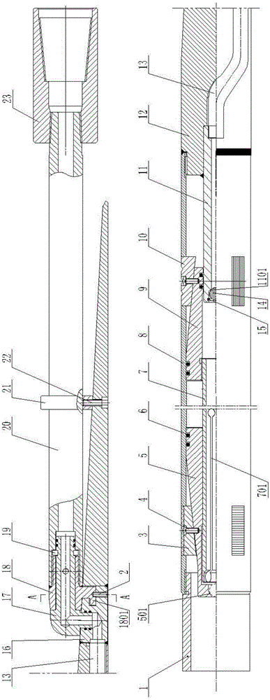
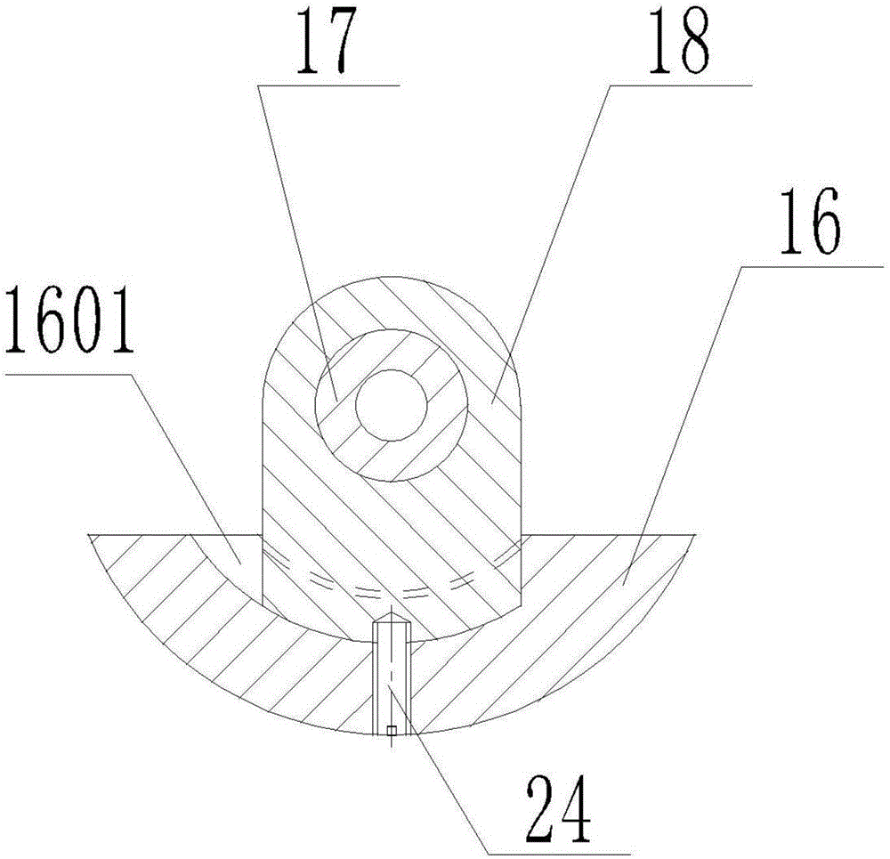
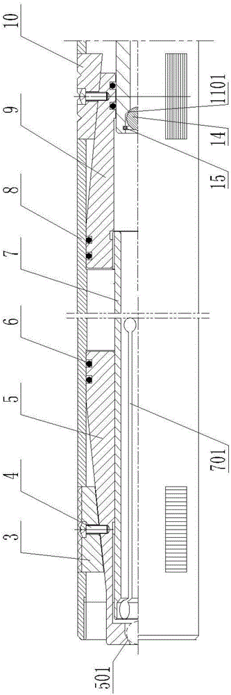
[0025] Such as Figure 1-Figure 3 As shown, the present invention relates to a hydraulic solid whip guide, including a tubular feeder 20, the upper end of the feeder 20 is screwed with an upper joint 23, and the lower end of the feeder 20 is sequentially connected with a whipstock angle iron 12 and the setting and anchoring device. A catheter 13 connecting the inner hole of the feeder 20 and the inner cavity of the setting and anchoring device is provided in the inclined iron 12 of the whip guide. At the lower end of the feeder 20, a hook body 18 is screwed and welded and fixed, and an elbow body 17 is inserted into the hook body 18. The upper end of the elbow body 17 penetrates the central hole of the hook body 18 and is sealed and inserted into the feeder 20. In the central hole of the elbow body 17, an annular groove is provided on the upper part of the outer edge of the elbow body 17, and a split snap ring 19 is provided in the annular groove between the upper end of the ho...


PUM


Abstract

The invention discloses a hydraulic solid wedge deflection tool, comprising a tubular feeder; the lower end of the feeder is orderly connected with a wedge deflection tool tapered iron and a seat seal anchoring device; a fluid guide pipe for interconnecting an inner hole of the feeder with an inner cavity of the seat seal anchoring device is arranged in the wedge deflection tool tapered iron; the lower end of the fluid guide pipe is interconnected with a jet flow pipe in the seat seal anchoring device; the lower end of the inner hole of the jet flow pipe is provided with a seat seal ball, and the lower end in the jet flow pipe is provided with a limiting structure or a limiting rubber belt, thus the seat seal ball is buckled at an upper buckle edge in drilling; the lower end of the inner hole of the lower cone of the seat seal anchoring device is provided with a lower annular buckle edge; when the seat seal ball is sealed, the seat seal ball can break through the limiting structure or the limiting rubber belt and fallen down under the pushing effect of high pressure drilling fluid and then blocked the lower buckling edge, so as to realize the seat seal. The wedge deflection tool can avoid false seat seal in the midway for the drilling fluid generates exciting pressure in the drilling process, and also avoid the false seat seal in midway by the suction of too quick drilling; the hydraulic solid wedge deflection tool is reliable in work, and can improve the working efficiency and reduce the working cost.

Description

Technical field [0001] The invention belongs to an oil field workover tool, and particularly relates to a hydraulic solid whip guide. Background technique [0002] The whip guide is a tool used for sidetracking in the well. The existing solid whip guide consists of a joint with a through hole, connected to the feeder at the outlet of the connector, and fixed on the outer wall of the feeder The inclined iron of the whip guide, the cylinder liner fixedly connected to the lower end of the inclined iron of the whip guide, the upper and lower cones, the horizontal slips and the longitudinal slips arranged in the cylinder liner, which are inserted into the limit positions in the upper and lower cones The tube is composed of a hook body connected at the exit of the feeder and an elbow body inserted in the hook body. Because of the restriction of the circulation channel, the one-way valve is pre-positioned in the lower part of the lower cone. The drilling fluid in the borehole will push...

Claims


Application Information

Patent Timeline
Patent Type & Authority Applications(China)
IPC IPC(8): E21B7/06
CPCE21B7/061
Inventor 张岚张凯峰张欣悦
Owner JINZHOU QINGHUA MACHINERY
Why Eureka
Try Eureka