Electrical connector

a technology of electrical connectors and latch locks, applied in the direction of electrical apparatus, connection, coupling device connection, etc., can solve the problems of plastic deformation of the arm member, damage or etc., to prevent the movement of the latch lock claw rotary, prevent the non-constant movement of the latch lock claw, and reduce the risk of damage and breakage of the electrical connector

Inactive Publication Date: 2014-09-18
DAIICHI SEIKO CO LTD
View PDF4 Cites 3 Cited by
  • Summary
  • Abstract
  • Description
  • Claims
  • Application Information

AI Technical Summary

Benefits of technology

[0016]In the arrangement relation of the present invention having such a configuration, when non-constant force such as pulling force in a direction other than the original insertion / removal direction is applied to the signal transmission medium inserted in the insulating housing, the latch lock claw tries to carry out rotary movement with respect to the supporting point at which elastic displacement of the lock arm member is carried out. Also in this case, part of the lock arm member abuts the lock-arm regulating part, thereby preventing rotary movement of the latch lock claw and reducing the risks of damage and breakage of the electrical connector.
[0017]As described above, the electrical connector according to the present invention employs a configuration provided with the lock-arm regulating part that regulates non-constant movement different from the specified movement of the latch lock claw, which carries out the specified movement so as to be engaged with or detached from the signal transmission medium inserted in the insulating housing, and the lock-arm regulating part is disposed so as to be opposed to the lock arm member in the two directions including the insertion / removal direction of the signal transmission medium and the insertion / removal orthogonal direction. Therefore, when non-constant external force such as pulling force in a direction different from the original insertion / removal direction is applied to the signal transmission medium inserted in the insulating housing, part of the lock arm member is configured to abut the lock-arm regulating part and prevent non-constant movement of the latch lock claw. Therefore, with the simple configuration, the risks of damage and breakage such as plastic deformation of the lock arm member can be well prevented, and usage durability of the electrical connector can be significantly improved at low cost.

Problems solved by technology

However, if external force is applied in a non-constant direction, for example, if the signal transmission medium (FPC, FFC, or the like) inserted in the insulating housing is pulled in a direction different from the original insertion / removal direction, the lock arm member may be elastically displaced toward a non-constant direction shifted from a specified moving direction by the non-constant external force, and the electrical connector may be damaged or broken, for example, the lock arm member may be plastically deformed.

Method used


Image

  • Electrical connector
  • Electrical connector
  • Electrical connector

Examples


Embodiment Construction

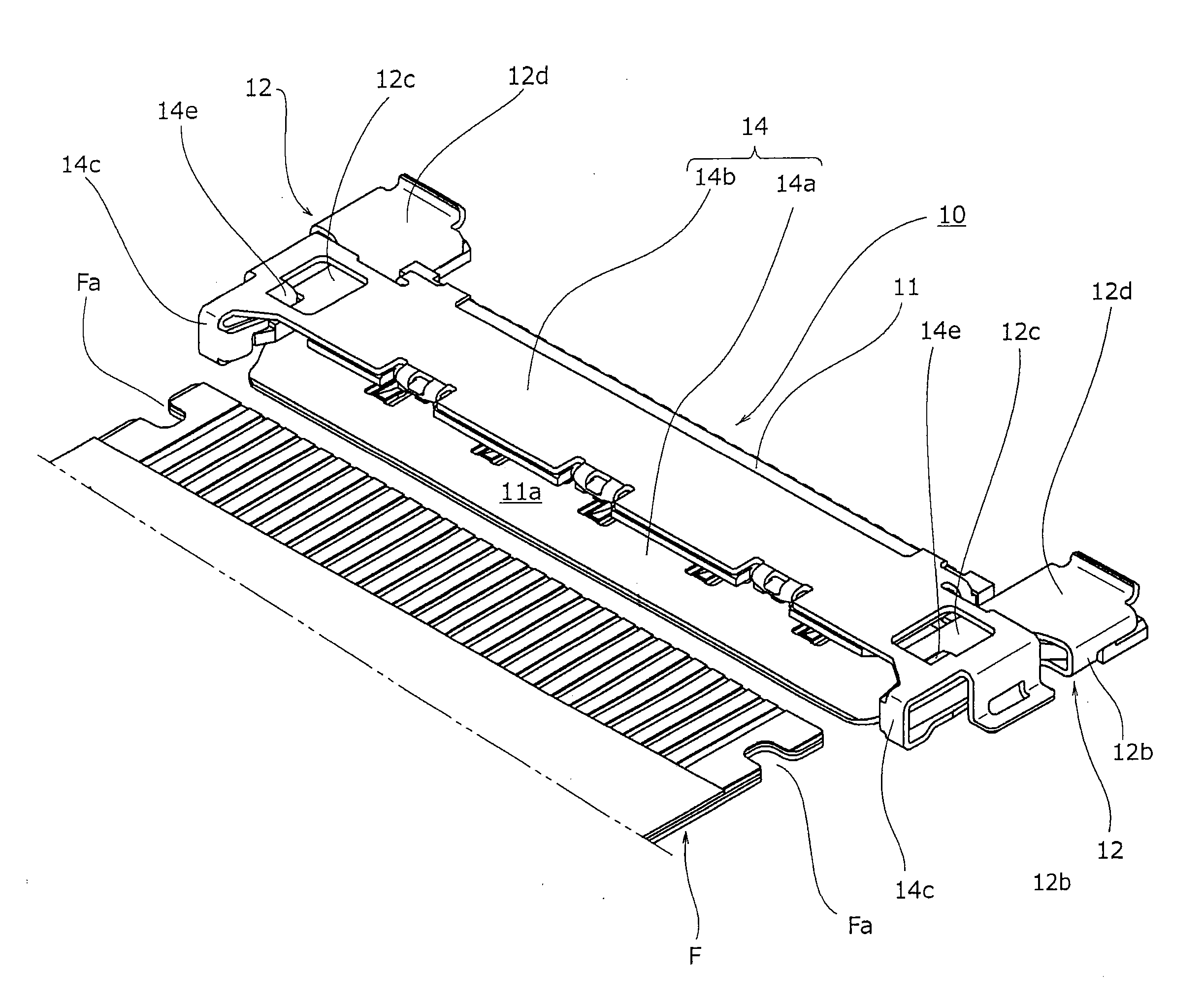
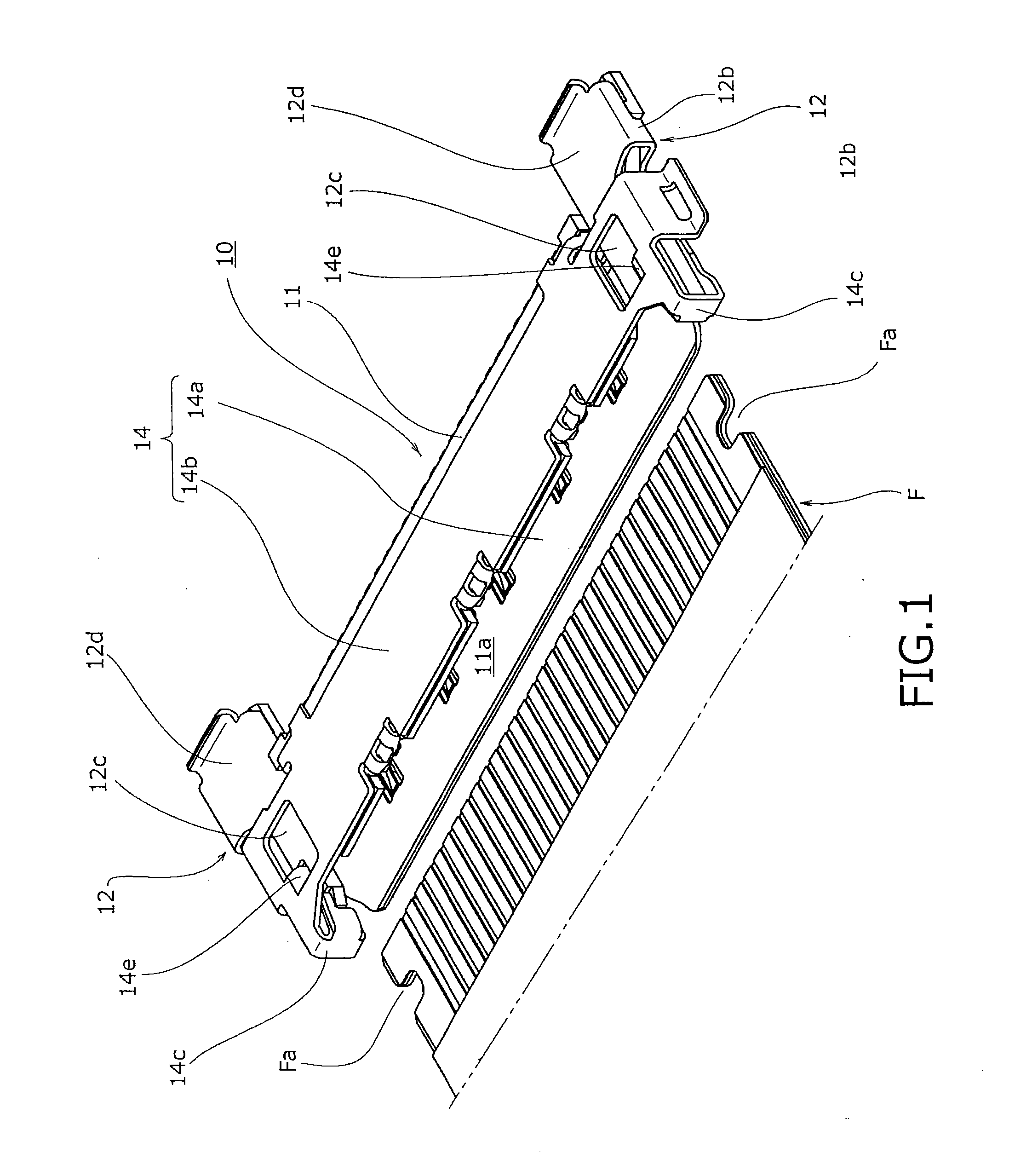
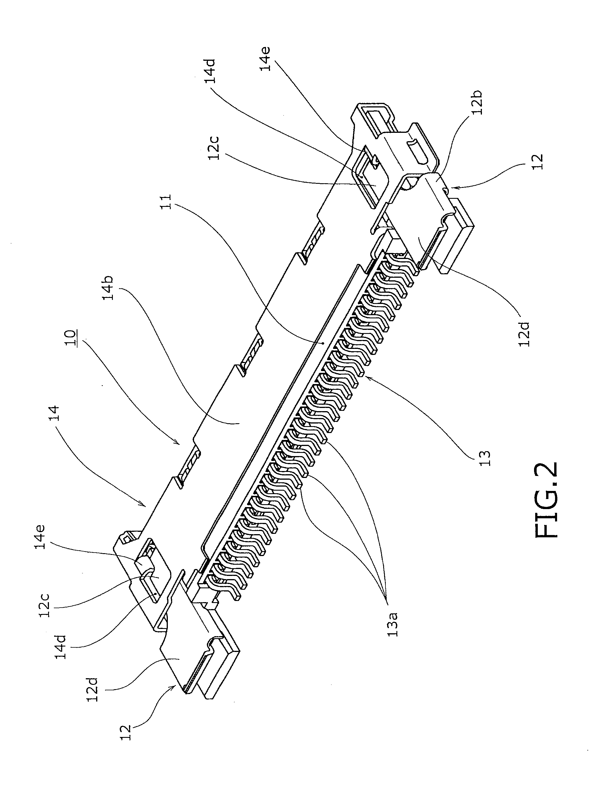
[0031]Hereinafter, an embodiment in which the present invention is applied to an electrical connector, which is used by being mounted on a wiring board in order to establish electrical connection of a signal transmission medium comprised of a flexible printed circuit (FPC), a flexible flat cable (FFC), or the like, will be explained in detail based on drawings.

[About Overall Configuration of Electrical Connector According to First Embodiment]

[0032]An electrical connector 10 according to an embodiment of the present invention shown in FIG. 1 to FIG. 13 is comprised of an electrical connector of a NON-ZIF type provided with a so-called one-action auto-lock mechanism and is configured to automatically lock the signal transmission medium F when a terminal part of the above described signal transmission medium (FPC, FFC, or the like) F is inserted to a predetermined position in an insulating housing 11 through a medium insertion opening 11a provided at a front edge part (left edge part i...


PUM


Abstract

The risks of damage and breakage such as plastic deformation of a lock arm member can be well prevented by a simple configuration. A lock-arm regulating part, which carries out regulation so that a latch lock claw for carrying out specified movement so as to be engaged with or detached from a signal transmission medium inserted in an insulating housing does not carry out non-constant movement different from the specified movement, is provided. The lock-arm regulating part is disposed to be opposed to the lock arm member in two directions including an insertion/removal direction of the signal transmission medium and an insertion/removal orthogonal direction. Since this configuration is employed, when non-constant external force such as pulling force in a direction different from the original insertion/removal direction is applied to the signal transmission medium, part of the lock arm member is configured to abut the lock-arm regulating part and prevent non-constant movement of the latch lock claw.

Description

BACKGROUND OF THE INVENTION[0001]1. Field of the Invention[0002]The present invention relates to an electrical connector configured to retain a signal transmission medium when a latch lock claw is engaged with the signal transmission medium inserted in an insulating housing.[0003]2. Description of Related Art[0004]Generally, in various electric devices, etc., as means for electrically connecting various signal transmission media such as flexible printed circuits (FPC) and flexible flat cables (FFC), various electrical connectors are widely used. For example, as electrical connectors used by being mounted on printed wiring boards like Japanese Patent Application Laid Open No. 2011-108500 and Japanese Patent Application Laid Open No. 2011-108501, those employing a so-called one-action auto-lock mechanism have been recently used. In such a lock mechanism, a latch lock claw elastically displaceably supported by a lock arm member is placed on the surface of the signal transmission medium...

Claims


Application Information

Patent Timeline
Patent Type & Authority Applications(United States)
IPC IPC(8): H01R12/70
CPCH01R12/7029H01R12/774
Inventor ISHIMARU, MASAO
Owner DAIICHI SEIKO CO LTD
Why Eureka
Try Eureka