Acoustic wave device
a wave device and waveguide technology, applied in the field of acoustic wave devices, can solve the problems of deteriorating passband characteristics, spurious emission, and insufficient suppression of spurious emission, and achieve the effect of suppressing spurious emission and superior passband characteristics
- Summary
- Abstract
- Description
- Claims
- Application Information
AI Technical Summary
Benefits of technology
Problems solved by technology
Method used
Image
Examples
exemplary embodiment 1
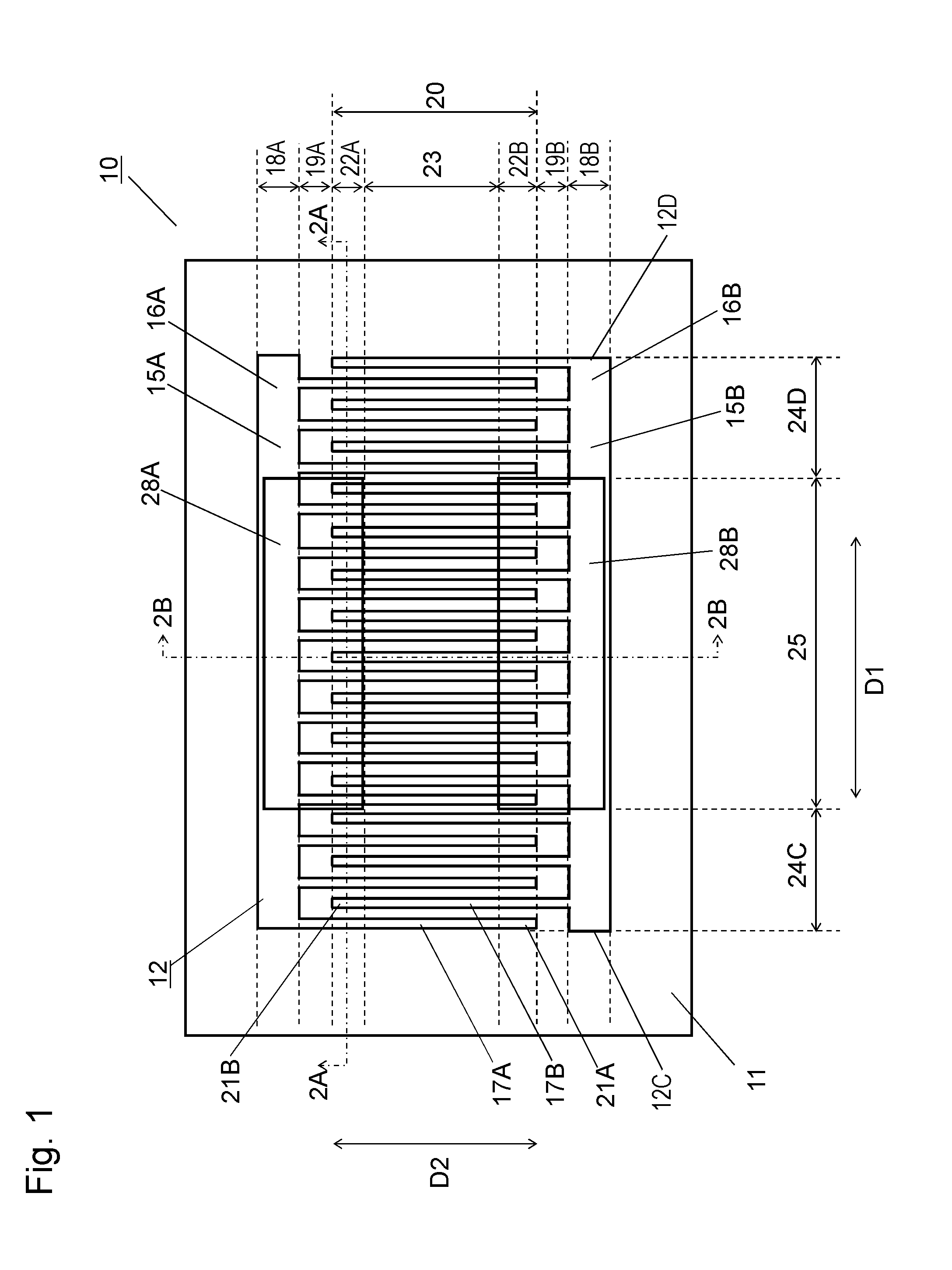
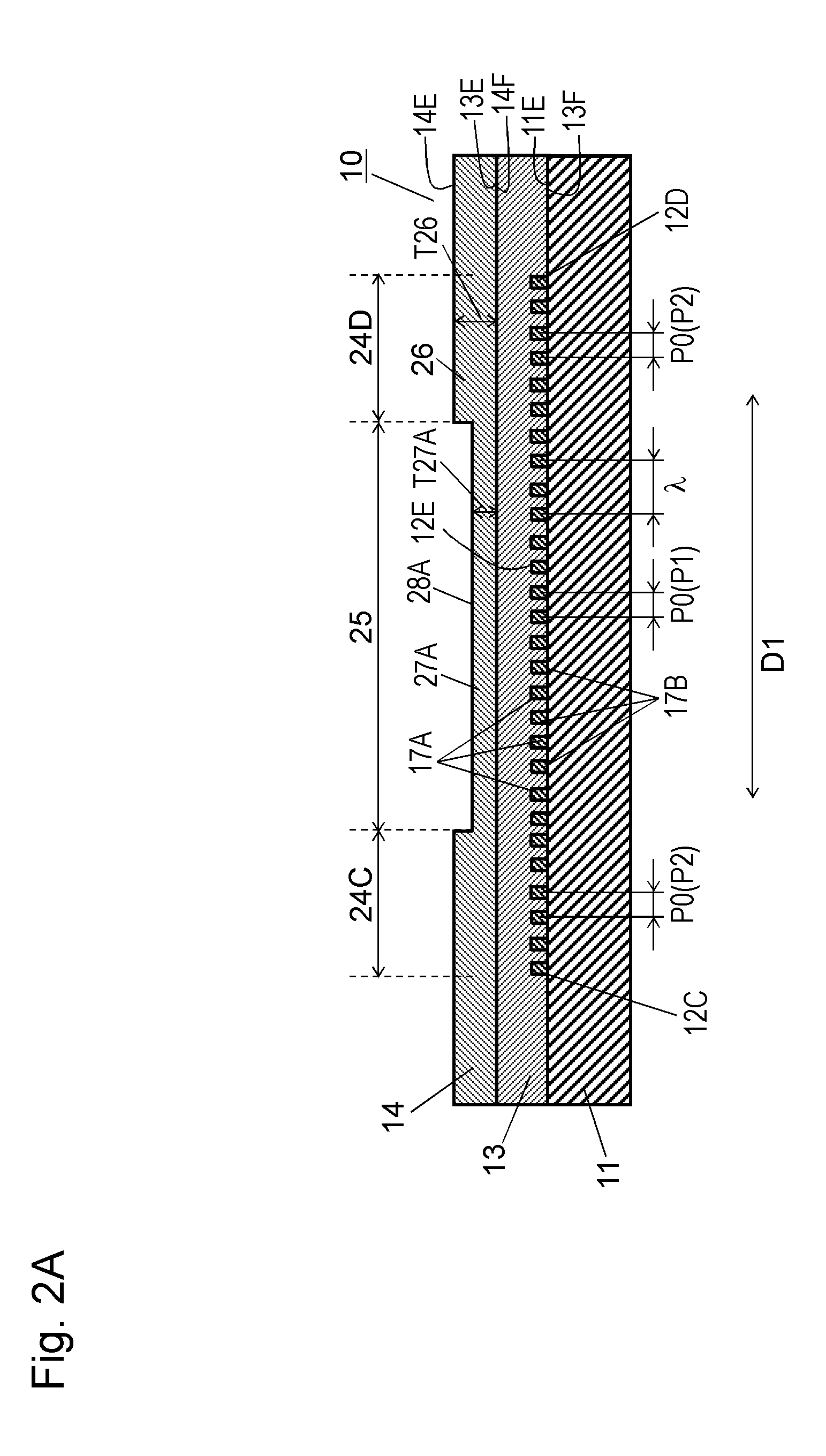
[0022]FIG. 1 is a schematic top view of acoustic wave device 10 according to Exemplary Embodiment 1 of the present invention. FIG. 2A is a cross-sectional view of acoustic wave device 10 at line 2A-2A shown in FIG. 1. FIG. 2B is a cross-sectional view of acoustic wave device 10 at line 2B-2B shown in FIG. 1.
[0023]Acoustic wave device 10 includes piezoelectric substrate 11, interdigital transducer (IDT) electrode 12 provided on upper surface 11E of piezoelectric substrate 11, dielectric film 13 provided on upper surface 12E of IDT electrode 12, and dielectric film 14 provided on upper surface 13E of dielectric film 13. Dielectric film 13 covers upper surface 11E of piezoelectric substrate 11 to cover IDT electrode 12. IDT electrode 12 includes a pair of comb electrodes 15A and 15B facing each other. Comb electrode 15A includes bus bar 16A and electrode fingers 17A extending from bus bar 16A toward comb electrode 15B in extending direction D2. Comb electrode 15B includes bus bar 16B a...
exemplary embodiment 2
[0043]FIG. 3 is a schematic depiction of a top view of acoustic wave device 40 according to Exemplary Embodiment 2 of the present invention. FIG. 4A is a schematic cross-sectional view of acoustic wave device 40 at line 4A-4A shown in FIG. 3. FIG. 4B is a schematic cross-sectional view of acoustic wave device 40 at line 4B-4B shown in FIG. 3.
[0044]In FIGS. 3, 4A and 4B, components identical to those of acoustic wave device 10 according to Embodiment 1 shown in FIGS. 1, 2A and 2B are denoted by the same reference numerals.
[0045]Acoustic wave device 40 according to Embodiment 2 is a one-terminal-pair resonator further including reflectors 29C and 29D provided at ends of IDT electrode 12 opposite to each other in propagation direction D1. Thus, IDT electrode 12 is provided between reflectors 29C and 29D in propagation direction D1.
[0046]Reflectors 29C and 29D reflect the main acoustic wave to confine the main acoustic wave in acoustic wave device 40. Reflectors 29C and 29D are made of ...
exemplary embodiment 3
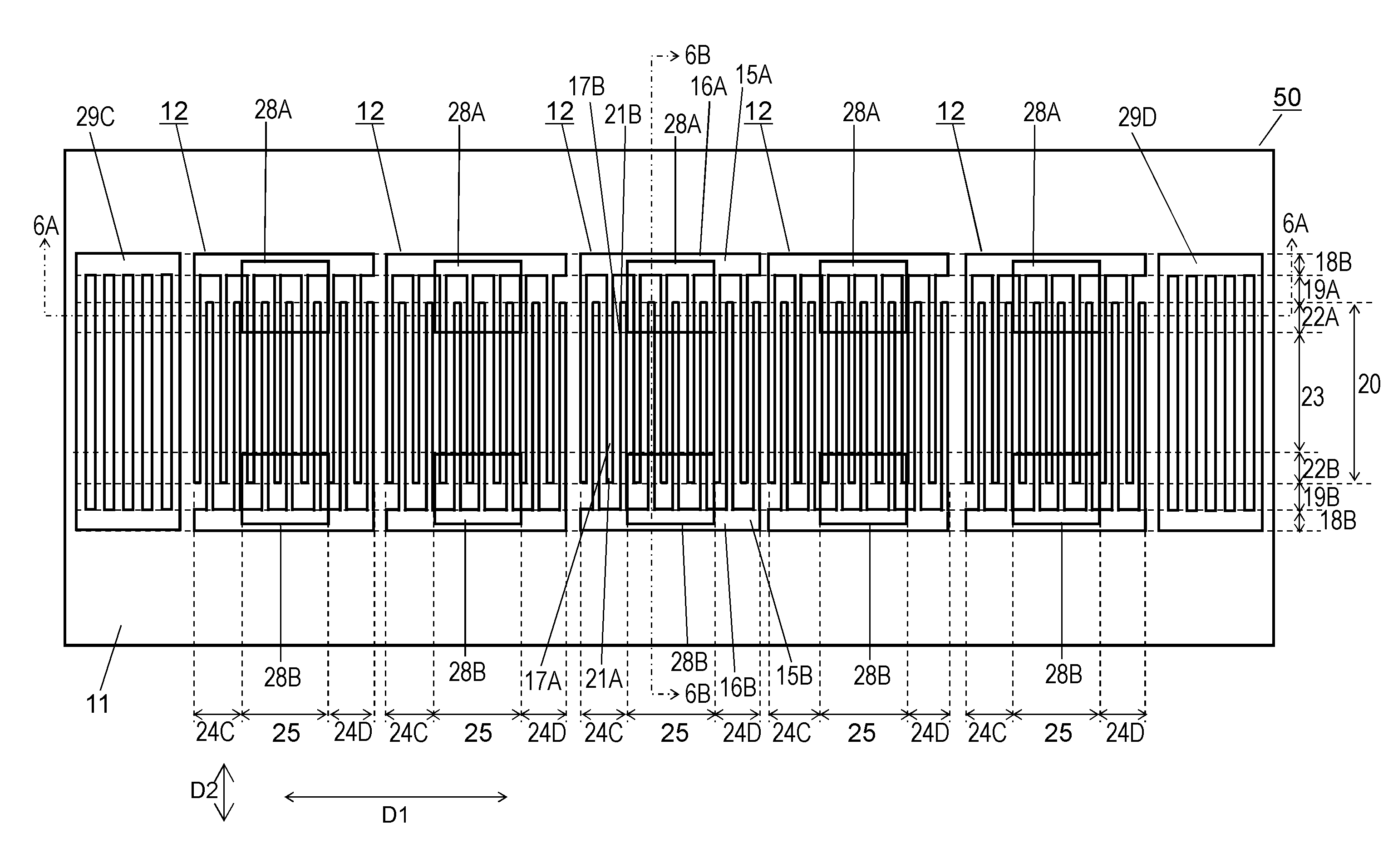
[0048]FIG. 5 is a top view of acoustic wave device 50 according to Exemplary Embodiment 3 of the present invention. FIG. 6A is a cross-sectional view of acoustic wave device 50 at line 6A-6A shown in FIG. 5. FIG. 6B is a cross-sectional view of acoustic wave device 50 at line 6B-6B shown in FIG. 5. FIG. 7 is a top view of a comparative example, acoustic wave device 60. FIG. 8A is a cross-sectional view of acoustic wave device 60 at line 8A-8A shown in FIG. 7. FIG. 8B is a cross-sectional view of acoustic wave device 60 at line 8B-8B shown in FIG. 7. In FIGS. 5, 6A, 6B, 7, 8A and 8B, components identical to those of acoustic wave device 40 according to Embodiment 2 shown in FIGS. 3, 4A and 4B are denoted by the same reference numerals. Acoustic wave devices 50 and 60 are longitudinally-coupled acoustic wave filters in which IDT electrodes 12 are arranged between reflector 29C and 29D in propagation direction D1.
[0049]Each of acoustic wave devices 50 and 60 includes piezoelectric subs...
PUM
 Abstract
Description
Claims
Application Information
 - R&D
- Intellectual Property
- Life Sciences
- Materials
- Tech Scout
- Unparalleled Data Quality
- Higher Quality Content
- 60% Fewer Hallucinations
Browse by: Latest US Patents, China's latest patents, Technical Efficacy Thesaurus, Application Domain, Technology Topic, Popular Technical Reports.
© 2025 PatSnap. All rights reserved.Legal|Privacy policy|Modern Slavery Act Transparency Statement|Sitemap|About US| Contact US: help@patsnap.com


