
Portable Doorway Recreation Apparatus

a doorway and recreation technology, applied in the field of portable doorway recreation equipment, can solve the problems of falling apparatus, inadequate under significant or abrupt side to side,

Active Publication Date: 2014-10-09
VELIKIN PETER HRISTOV +1
View PDF8 Cites 60 Cited by
  • Summary
  • Abstract
  • Description
  • Claims
  • Application Information

AI Technical Summary

Benefits of technology

The invention is a device that can be attached to a doorway frame to create a temporary recreational space. It consists of an L-shaped frame, two horizontal bars that are attached to the frame, and a securing member that attaches to the second horizontal bar. The device can be easily attached to a doorway frame to provide a secure and stable platform for activities such as yoga, fitness classes, and outdoor parties. The technical effect of this invention is that it allows for the creation of a portable and flexible recreational space without the need for expensive and permanent installations.

Problems solved by technology

However, horizontal loads which may be introduced, by way of example, by swinging, can cause the horizontal member to disengage from the top of the door trim, causing the apparatus to fall.
While this safety lock provides some stability under horizontal loads, it is inadequate under significant or abrupt side to side swinging motion loads such as might be present with a swing or a punching bag mounting to the portable chinning bar assembly of Winblad, or from any athletic exercises involving full-body motion swinging.

Method used


Image

  • Portable Doorway Recreation Apparatus
  • Portable Doorway Recreation Apparatus
  • Portable Doorway Recreation Apparatus

Examples


second embodiment

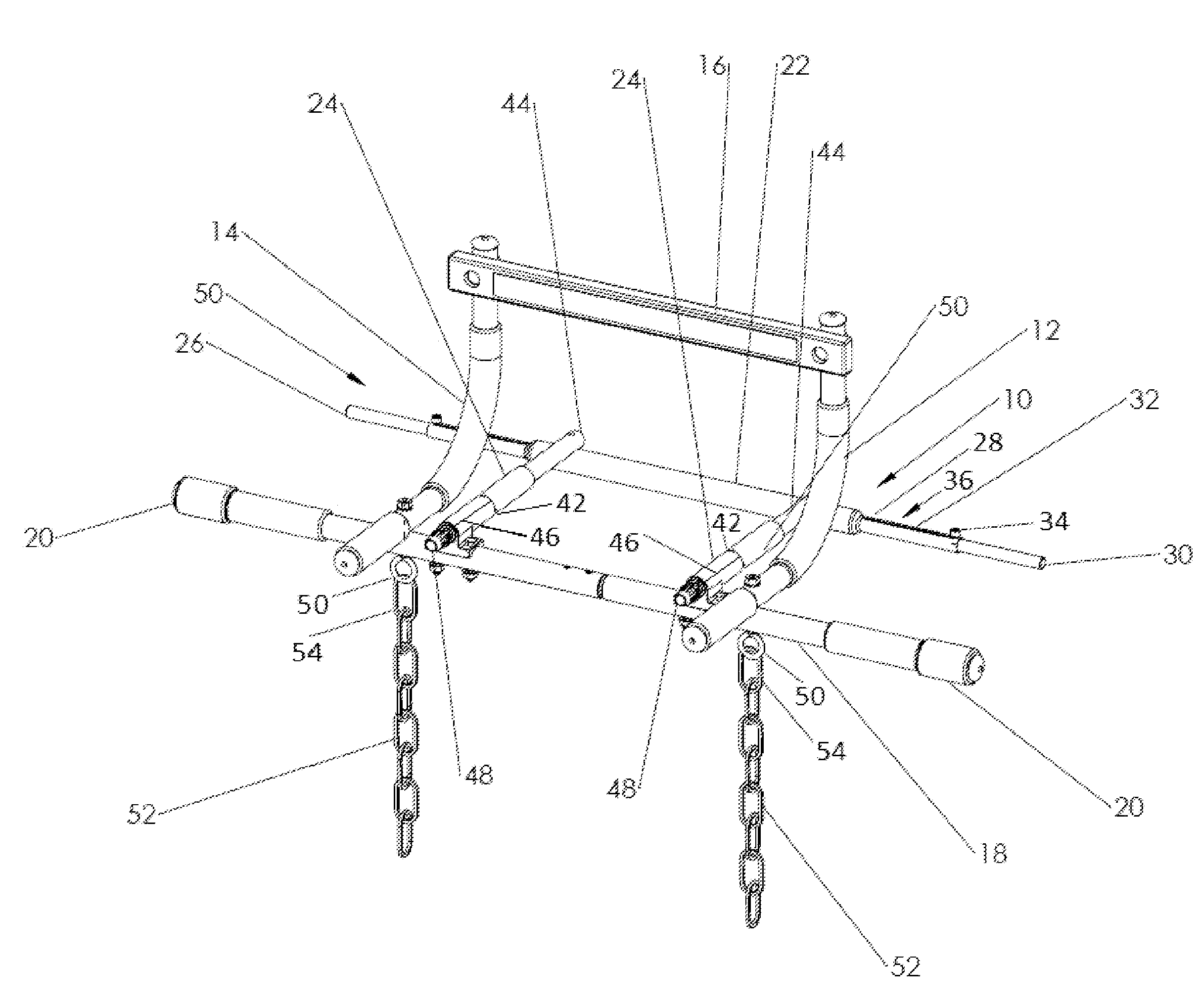
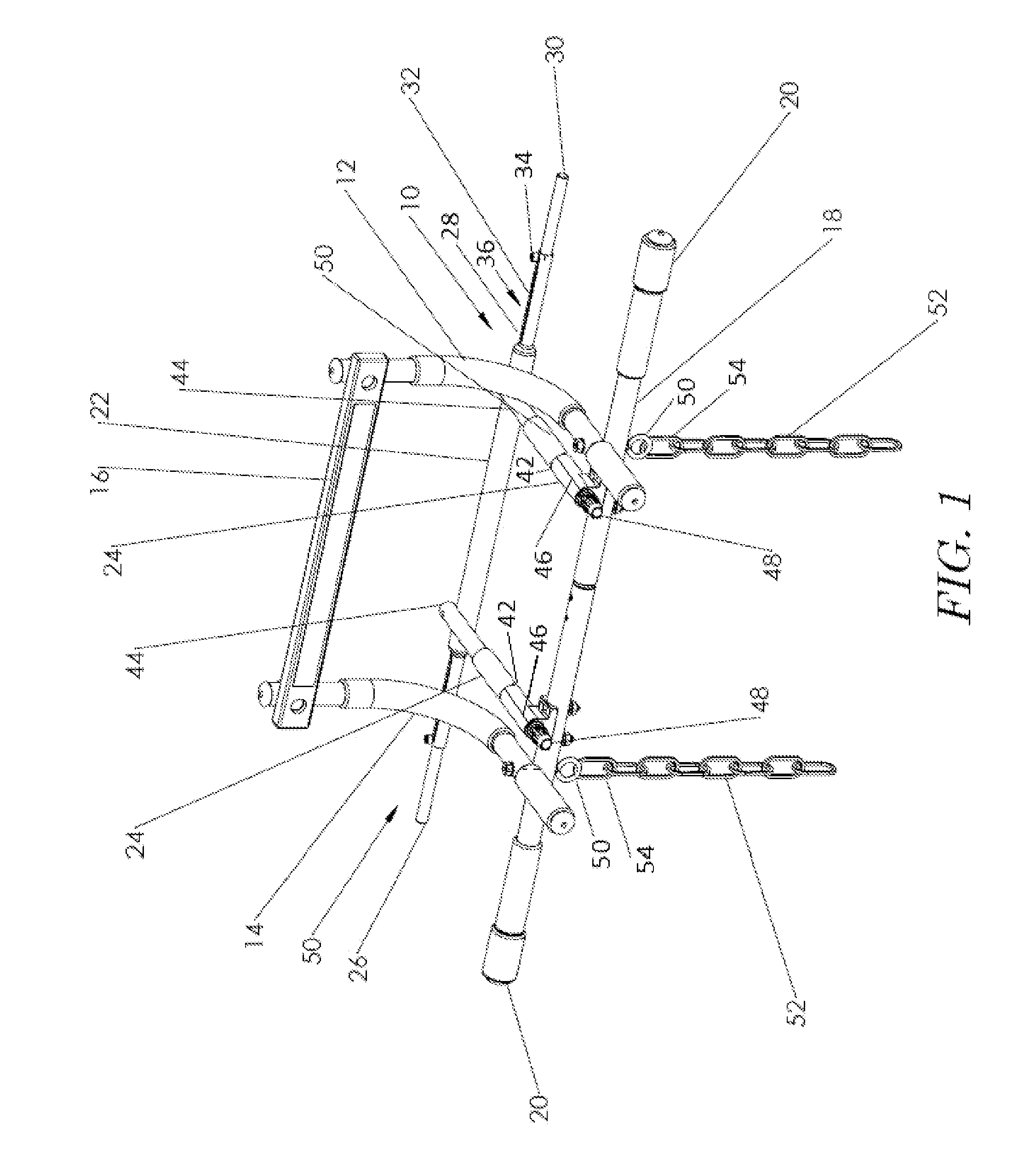
[0057]FIG. 8 shows the portable doorway recreation device. The two L-shaped bars 12,14 are spaced apart with the first elongate bar 16 attached to the risers of the L-shaped bars and the second elongate bar 18 attached to the base of the L-shaped bars. A securing member comprises a rectangular pad 801 attached to the base of the L-shaped bars 12, 14 by struts 803,805. More particularly, a first end of each strut 803,805 is pivotably mounted to the base of the L-shaped bar distal of the second elongate bar 18 and the rectangular pad 801 is pivotably attached at opposite ends to the second ends of the struts 803,805. A turnbuckle 807,809 joins each strut to the base of the L-shaped bar proximate the second elongate bar 18. In one embodiment a first end of the turnbuckle is pivotably attached proximate the second elongate bar 18 and the second end of the turnbuckle comprises an eyelet 811 which can selectively receive the post 813 on the struts 803,805. A spring 815 may optionally be p...

third embodiment

[0062]FIG. 12 shows the third embodiment properly deployed in a doorway from view of the second wall side. The first elongate bar is hidden from view.

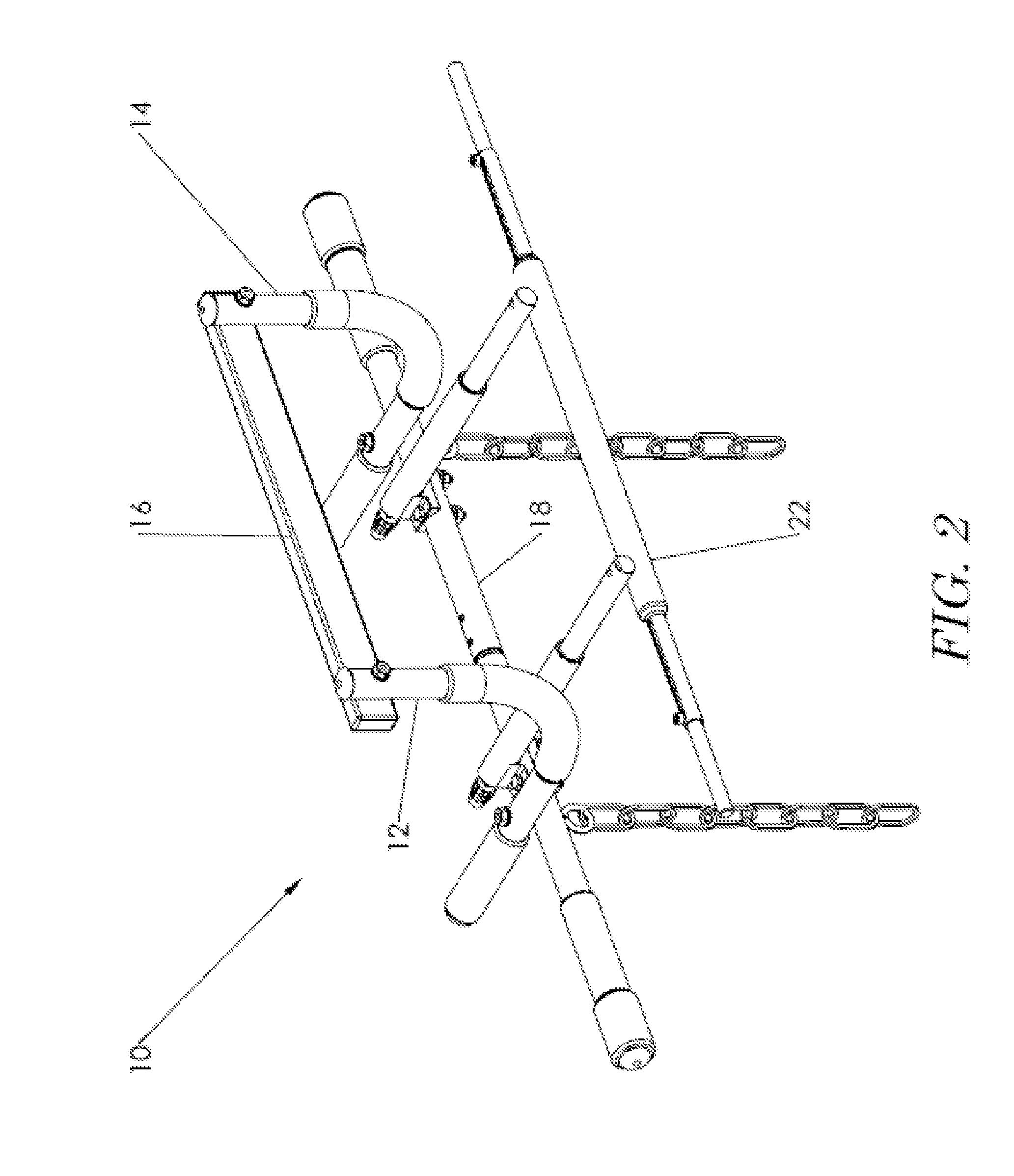
[0063]FIG. 13 shows a detailed side elevation of the second embodiment mounted on a doorway frame. The L-shaped bar 12 is attached to a first elongate bar 16 is shown on a first wall side. As deployed, the first elongate bar 16 hooks on top of the doorway frame. The second elongate bar 18 abuts the second side of the wall on opposite sides of the doorway. The rectangular pad 801 connected to the struts 805 is pivoted toward the second wall side by a turnbuckle 807.

[0064]FIG. 14 shows a detailed front elevation of the second embodiment. The rectangular pad 801 is held by struts 803, 805. On each strut, an eyelet 813 and hook 811 of the turnbuckle assembly (hidden) maintain the elevated position of the struts 803, 805 and rectangular pad 801 above the doorway. The second elongate bar 18 is flush against the doorway frame and supported by...


PUM

PropertyMeasurementUnit
squeezing forceaaaaaaaaaa
angular momentumaaaaaaaaaa
forceaaaaaaaaaa

Abstract

A portable doorway recreation device for use on a doorway frame comprises an L-shaped frame. A first horizontal elongate bar is attached to a riser of the L-shaped frame and a second horizontal elongate bar is attached to a base of the L-shaped frame. A securing member is operatively associated with the second elongate bar, wherein with the first elongate bar sitting on a top of the doorway frame on a first wall side and the second elongate bar operatively associated with a second wall side, the securing member is configured to engage one of the first and second wall sides to prevent movement of the second elongate bar away from the second wall side.

Description

RELATED APPLICATIONS[0001]This continuation-in-part application claims priority from International Application Serial No. PCT / US11 / 54925, filed Oct. 5, 2011, entitled, “Portable Doorway Recreation Apparatus,” which claims priority from U.S. Provisional Patent Application Ser. No. 61 / 389,826, filed Oct. 5, 2010, entitled “Portable Doorway Recreation Apparatus,” both of which are hereby incorporated by reference.TECHNICAL FIELD[0002]The present disclosure is directed to a portable doorway recreation apparatus and more particularly to a portable doorway recreation apparatus configured to securely support associated recreation and athletic equipment under vertical, horizontal and combined vertical and horizontal static or dynamic loads.BACKGROUND[0003]A variety of portable doorway recreation apparatus are known in the art. Commonly these apparatus include generally L-shaped frames having a horizontal support attached to the riser of the L-shaped frame and a horizontal bar (often used as...

Claims


Application Information

Patent Timeline
Patent Type & Authority Applications(United States)
IPC IPC(8): A63B21/068A63B1/00
CPCA63B1/00A63B7/02A63B21/00047A63B21/1636A63B2208/0285A63B21/068A63G9/12A63B69/201A63B69/24A63B1/005A63B2210/54Y10T29/49826A63B69/305
Inventor VELIKIN, PETER HRISTOVALEXANDROV, KIRIL STEFAN
Owner VELIKIN PETER HRISTOV
Learn More