Eureka AIR delivers breakthrough ideas for toughest innovation challenges, trusted by R&D personnel around the world.

Electric vehicle

Active Publication Date: 2014-10-09
NTN CORP
View PDF13 Cites 10 Cited by
  • Summary
  • Abstract
  • Description
  • Claims
  • Application Information

AI Technical Summary

Benefits of technology

The patent text is about a challenge in using regenerative braking, which can cause a tire to slip, in electric vehicles. To address this, the patent proposes a method of controlling the allocation of braking torque between different wheels to avoid slip. The invention aims to make the best use of regenerative braking and prevent tire slip.

Problems solved by technology

Thus, compared with friction braking, excessive application of regenerative braking may result in the slip of a tire.
Therefore, it is a challenge to effect appropriate application of regenerative braking.
In particular, with an in-wheel motor drive system, a braking torque may be transmitted right onto its corresponding wheel, so that allocation of torque among different wheels may not be available.
However, a wheel may often lose contact with a road surface during travel.
Thus, appropriate control of a regenerative brake may be difficult based on detected values of a drive torque of a motor and / or a rotational speed of a wheel alone.

Method used


Image

  • Electric vehicle
  • Electric vehicle
  • Electric vehicle

Examples


Embodiment Construction

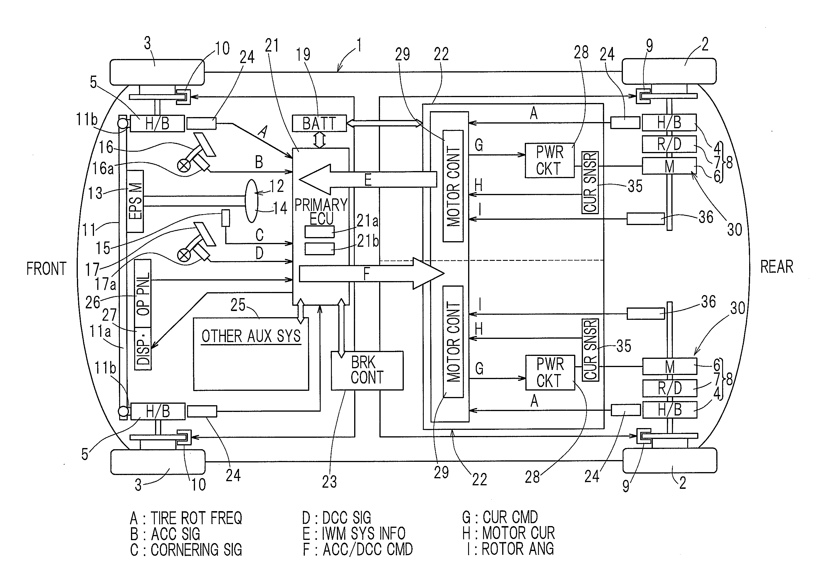
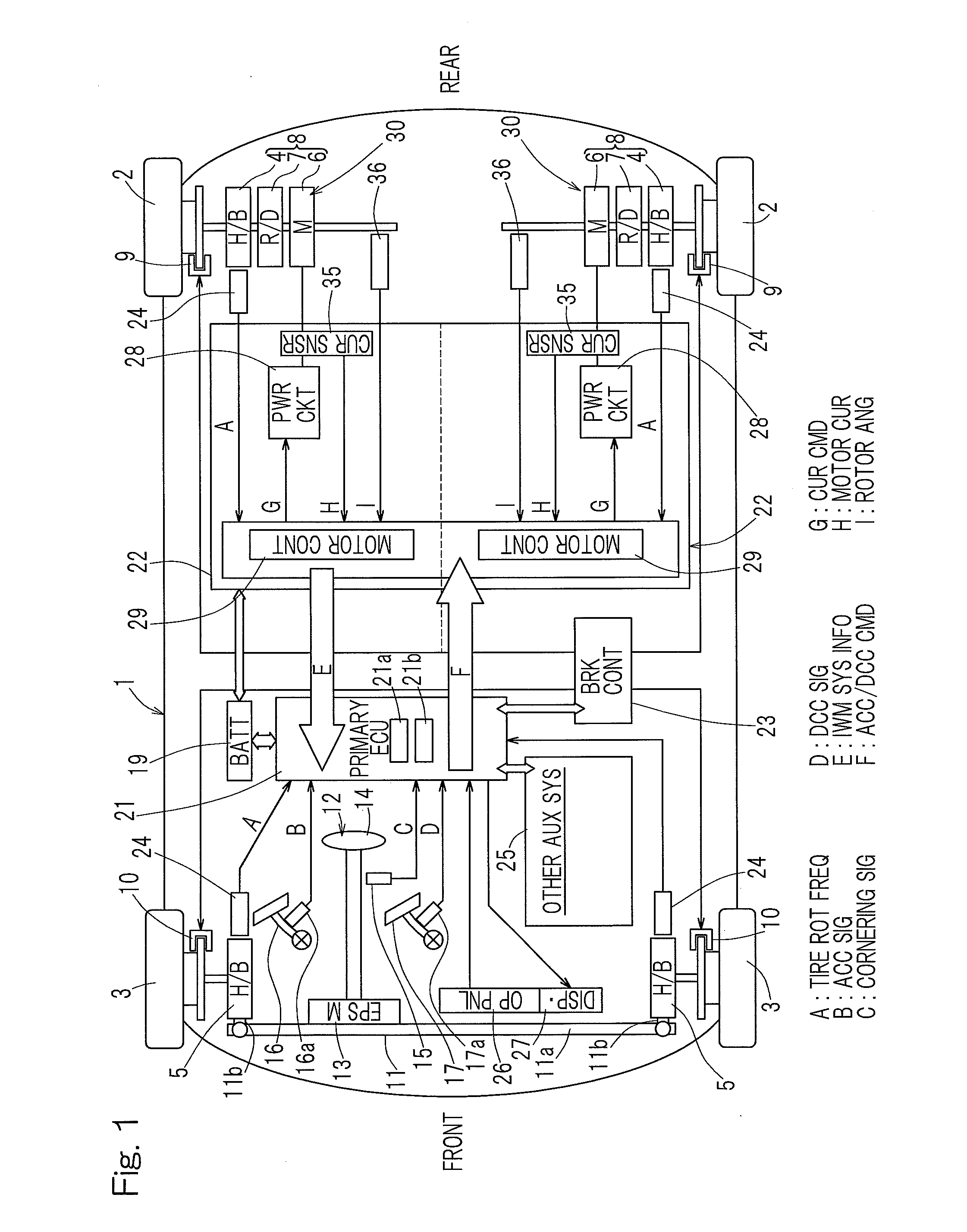
[0032]An embodiment of the present invention will now be described in connection with FIG. 1 to FIG. 11. The illustrated electric vehicle is a four-wheel vehicle that includes a vehicle body 1 with left and right rear wheels 2 and left and right front wheels 3, with the rear wheels being drive wheels and the front wheels being steered driven wheels. The wheels 2, 3—that is, drive wheels and driven wheels, respectively—are all equipped with tires and are supported by the vehicle body 1 via respective wheel bearing units 4, 5. In FIG. 1, the wheel bearing units 4, 5 are labeled with “H / B” which is an abbreviation for hub bearing. The left and right drive wheels 2, 2 may be driven by respective independent traction motor units 6, 6. Rotation of a motor unit 6 may be transmitted via a reducer unit 7 and through a wheel bearing unit 4 to a wheel 2. The motor unit 6, the reducer unit 7 and the wheel bearing unit 4 may be integrally assembled with each other to form an in-wheel motor drive...


PUM


Abstract

An electric vehicle includes a regenerative brake (34) and a mechanical brake (9). The vehicle also includes a wheel bearing unit (4) and a load sensor (41) associated with the wheel bearing unit (4). The load sensor (41) is configured to detect a load that acts between a road surface and a tire along a direction in which the vehicle travels. The vehicle also includes a load-responsive regenerative brake limiter (36) configured to reduce a braking torque generated by the regenerative brake (34) when an output of the load sensor (41) reaches a preset value. A maximally actuator (35) may be configured to calculate a maximum possible regenerative braking torque for the regenerative brake (34) based on a rotational frequency of a wheel and a state of charge of a battery unit and to actuate the regenerative brake at a maximum torque (34) within that commanded range.

Description

CROSS REFERENCE TO THE RELATED APPLICATIONS[0001]This application is based on and claims the Convention priority to a Japanese patent application No. 2011-254570, filed Nov. 22, 2011, the entire disclosure of which is herein incorporated by reference as a part of this application.BACKGROUND OF THE INVENTION[0002]1. Field of the Invention[0003]The present invention relates to an electric vehicle, such as an in-wheel motor vehicle, that is equipped with motor(s) to drive wheels and that may be battery-powered or fuel cell-powered.[0004]2. Description of Related Art[0005]An electric vehicle often employs an IPM motor (e.g., Interior Permanent Magnet synchronous motor) to increase the maximum travel distance that is possible with a limited battery capacity. This kind of motor is characterized by its ability to allow a regenerative braking operation to be performed with ease. Where the maximum travel range is a key issue, it may be desirable to utilize the regenerative brake as much as p...

Claims


Application Information

Patent Timeline
IPC IPC(8): B60L15/20
CPCB60L15/2009B60L1/003B60L3/102B60L3/108B60L7/14B60L7/18B60L7/26B60L15/2036B60L50/51B60L58/12B60L2220/44B60L2220/50B60L2240/12B60L2240/24B60L2240/26B60L2240/421B60L2240/423B60L2240/461B60L2240/465B60L2250/16B60L2250/26B60L2260/28B60T1/10B60T13/586B60T13/741B60T2240/06B60T2270/604F16D61/00Y02T10/64Y02T10/70Y02T10/72B60L7/24
Inventor OZAKI, TAKAYOSHI
Owner NTN CORP
Why Eureka
Eureka Blog
Learn More