Acid injection

a technology of injection and acid, applied in the field of acid injection, can solve the problems of seizing of the screw mechanism, high cost of well tree and parts, and additional cost of including a secondary release mechanism in the design of the stabplate connection

Active Publication Date: 2014-10-30
BAKER HUGHES ENERGY TECH UK LTD
View PDF4 Cites 3 Cited by
  • Summary
  • Abstract
  • Description
  • Claims
  • Application Information

AI Technical Summary

Problems solved by technology

Leaving the screw mechanism subsea for lengthy periods of time can result in corrosion and contamination (e.g. biological growths) which can cause the screw mechanism to seize.
The result is either the need for other forceful methods of separating the stabplate from the fixed plate (invariably resulting in expensive damage to the well tree and parts of the stabplate connection) or the...

Method used


Image

  • Acid injection
  • Acid injection
  • Acid injection

Examples


Embodiment Construction

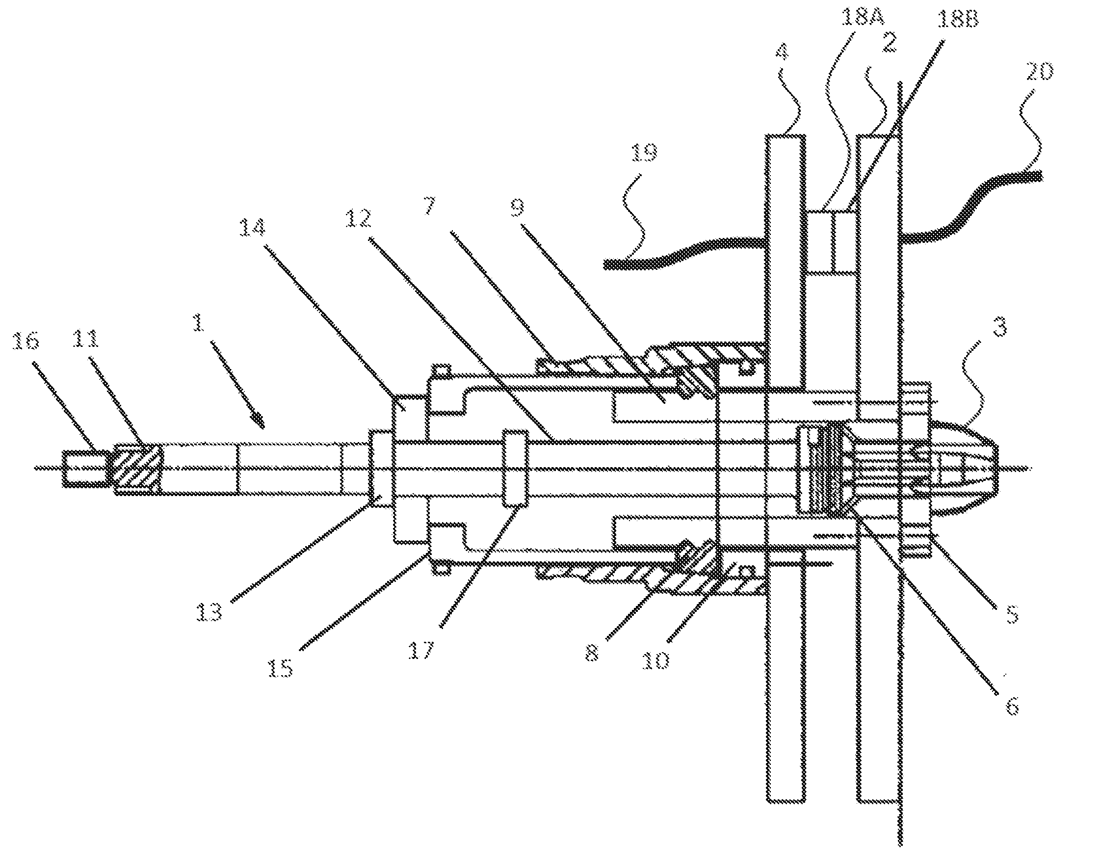
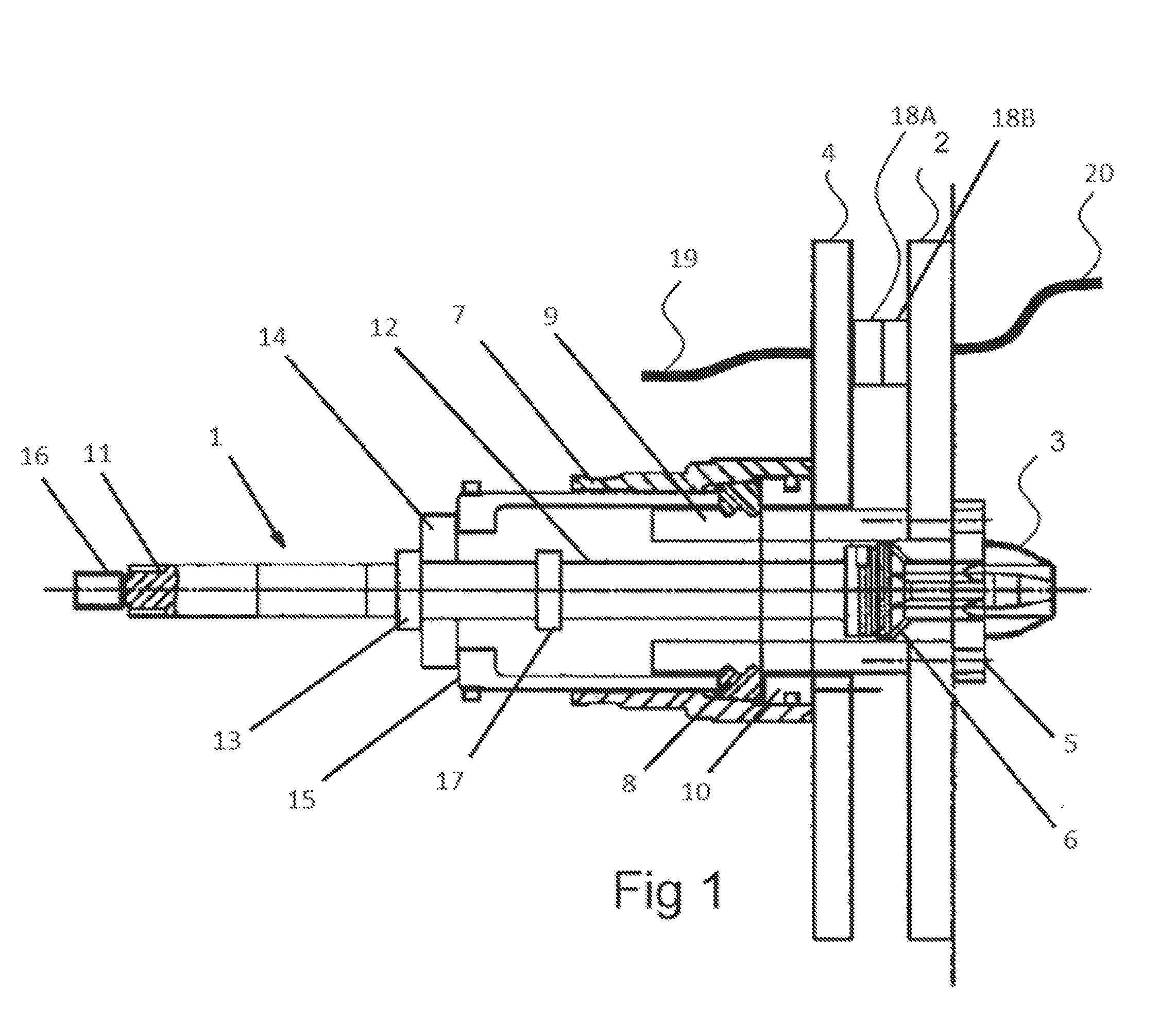
[0021]FIG. 1 shows a stabplate connection resulting from the teachings of GB-A-2473444, after completion of the mating of the plates as a result of mating of connectors carried by the plates. A retrievable tooling package 1 has been locked to a fixed plate 2 with a chamfered end 3 of the tooling package engaged with a stabplate 4 via an anchor block 5 and a tapered end portion 6 received in the tapered entrance to the orifice of anchor block 5. A bayonet locking collar 7 has been pushed forward, so that locking dogs 8 are forced to engage with grooves in tube 9, which is carried by fixed plate 2. The bayonet locking collar 7 has then been rotated to engage bayonet pins into a bayonet locking pin locator 10, thus mating the stabplate 4 to fixed plate 2. Subsequently, a threaded shaft 11 is rotated to unscrew from a tube 12 so that the force on the collar 13 and the latching / de-latching plate 14 on a dog support cage 15 is released, thus allowing a square-ended shaft 16 to be rotated ...


PUM


Abstract

A method of applying acid-wash to a subsea connection assembly, in particular a stabplate connection, in order to remove unwanted material such as marine growth and calcareous deposits. The method consists of inserting a plug, containing channels, into a central in a stabplate connection and injecting acid-wash through the plug. The plug may be carried by an operating tool arm of a remotely operated underwater vehicle (ROV).

Description

BACKGROUND OF THE INVENTION[0001]The present invention relates to injecting acid-wash into a subsea connection assembly, in particular for removing unwanted material.[0002]Electric and hydraulic power, chemical injection and communications are typically transmitted to subsea wells via an umbilical from a surface or land based platform, the umbilical being terminated at an umbilical termination assembly (UTA). The feeds for electric and hydraulic power and chemical injection are effected from the UTA to a well tree, which houses a well control system, by a multiplicity of self-sealing individual connectors. In order to facilitate mating or unmating of the electric and hydraulic power and chemical injection connectors subsea by a remotely operated underwater vehicle (ROV), they are typically mounted together on a plate known as a stabplate, so that a single ROV action mates all the connectors. Such a stabplate arrangement is normally reserved for the electric and hydraulic power and c...

Claims


Application Information

Patent Timeline
IPC IPC(8): E21B37/06
CPCE21B37/06E21B33/038E21B41/0007
Inventor VANGASSE, ANTHONY JASONLEWIS, GARETH HUW
Owner BAKER HUGHES ENERGY TECH UK LTD
Why Eureka
Try Eureka